Introduction :
The XT60 2+4 connector combines a main DC power connection with auxiliary circuits in one housing. For engineers designing a battery lead or equipment harness, the key question is what each contact is intended to carry. The "2+4" designation describes the contact layout; it does not provide a complete electrical pinout.
What Does XT60 2+4 Mean ?
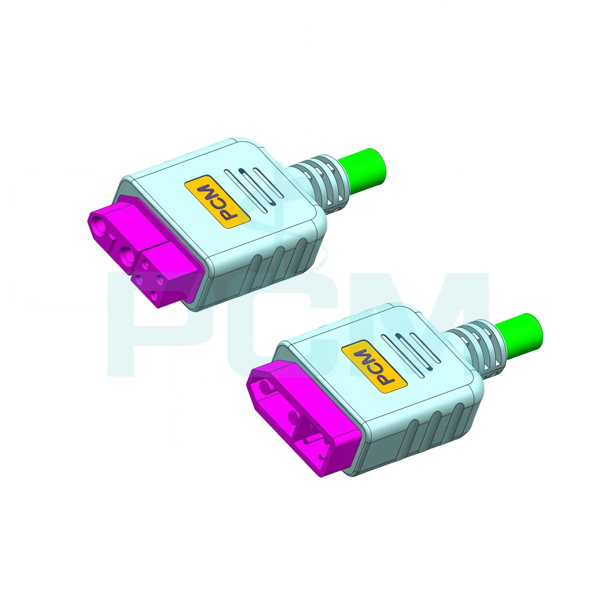
An XT60 2+4 connector has six contacts in two groups:
Two larger contacts: Used for the main power circuit, typically DC positive and DC negative.
Four smaller contacts: Used for lower-current auxiliary connections.
This arrangement allows one connector to carry power and additional circuits between a battery and connected equipment. Depending on the system, the smaller contacts may be assigned to voltage sensing, battery monitoring, temperature sensing, enable signals, or other control and feedback functions. These are possible uses, not universal assignments.
Do not confuse this six-contact configuration with the familiar two contact XT60 power connector. Standard XT60 documentation describes a two pin connector, while XT60 2+4 product listings describe a six contact layout. The two versions do not share the same pinout.
Is There an Internationally Recognized XT60 2+4 Pinout Standard ?
There is no generally accepted international pinout that can be assumed from the XT60 2+4 name alone. The designation identifies the connector family and contact arrangement; it does not define a universal function for each auxiliary contact.
The two larger contacts are generally used for the positive and negative power paths, but their polarity and orientation must still be checked against the connector drawing and equipment documentation. The four smaller contacts are application dependent. One system may use them for battery monitoring, while another may assign them to temperature feedback or control signals, or leave some positions unused.
For this reason, do not copy apinout from another battery pack, electronic speed controller (ESC), or power distribution board solely because it uses an XT60 2+4 connector. A matching contact layout does not guarantee matching electrical assignments.
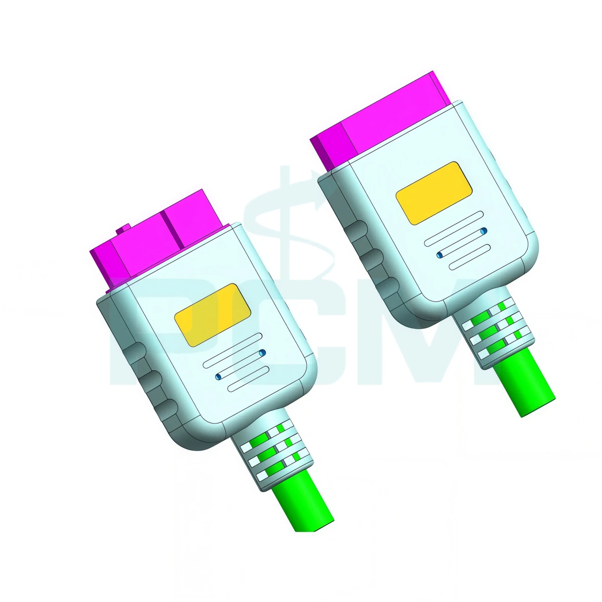
How Should You Confirm the Pinout ?
Before ordering or building a replacement cable, confirm the pin assignment for the actual equipment.
1. Identify the Exact Connector
Record the manufacturer, complete part number, male or female version, and mating connector. Obtain the drawing for that exact model. Check whether it shows the mating face or solder side; the contact positions may appear mirrored when viewed from the opposite side.
2. Check the Equipment Wiring Diagram
Use the battery, ESC, controller, or equipment manufacturer's wiring documentation as the primary reference. Confirm the positive and negative power contacts, then identify each auxiliary contact. Do not assign functions based only on contact size, position, or wire color.
3. Verify the Existing Harness
If the original cable is available, inspect its wire routing and check continuity with a multimeter while the equipment is disconnected and unpowered. Compare each wire with the connector position and equipment-side connection. Never use a live circuit or an unknown battery connection as a trial and error method for identifying pins.
4. Document and Test the Pinout
Create a pinout table showing the contact number, viewing direction, signal name, wire color, conductor size, and relevant electrical limits. Mark unused contacts clearly. Before connecting the finished cable, verify continuity, polarity, and unintended shorts against the approved wiring diagram.
Where Are XT60 2+4 Connectors Used ?
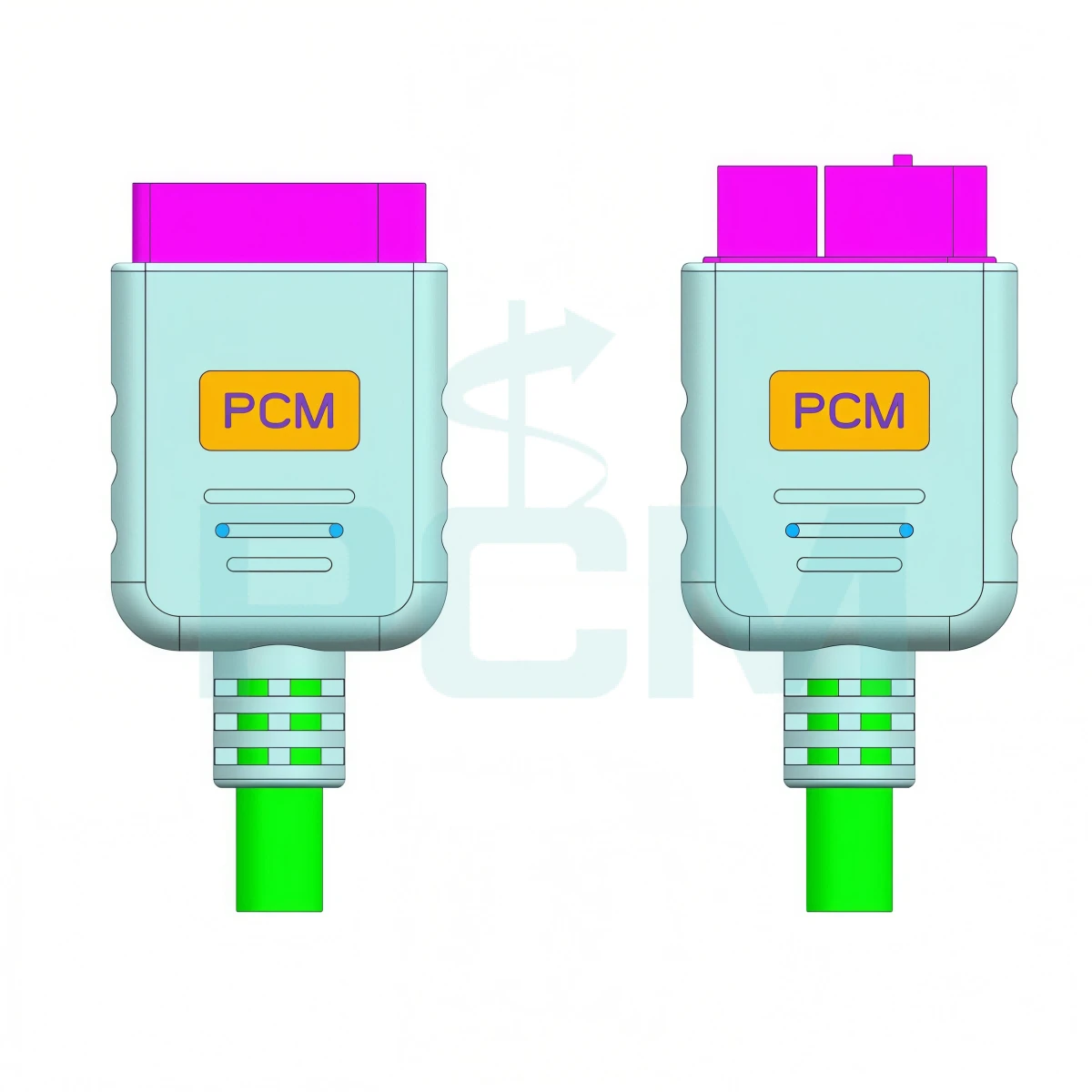
XT60 2+4 connectors are designed for battery powered systems that require both main DC power and auxiliary electrical connections through a single interface. The two larger contacts carry the primary power supply, while the four smaller contacts can accommodate application specific monitoring, feedback, or control circuits. This configuration is useful in compact equipment where power and auxiliary wiring need to be integrated into one cable assembly.
Typical applications include:
- FPV Drones and Multi rotor Drones
- RC Models and Model Aircraft
- Custom Battery Packs and Smart Battery Systems
- Battery Powered Robots and Mobile Devices
The equipment design determines which auxiliary contacts are required and how they are assigned.
Premier Cable Custom XT60 2+4 Cable Assemblies
Premier Cable can support custom XT60 2+4 cable assemblies based on the customer's equipment requirements and approved pinout. The assembly can be specified by connector version, contact assignment, cable length, conductor size, cable construction, and termination arrangement.
For a quotation, provide the connector part number or clear photos of both mating halves, the equipment model, a wiring diagram or pinout table, the required cable length, and operating conditions. An original cable can also help confirm connector orientation and wire to contact mapping.
A documented pinout is the starting point for a dependable XT60 2+4 cable assembly. Contact Premier Cable to discuss a cable built to your equipment's wiring requirements.
You Might Also Like
XT30 Round Panel Mount Extension Cable
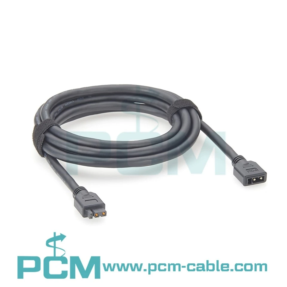
XT30 2+2 CAN Bus Extension Cable

XT60 D-Type Panel Mount Extension Cable