Micro-Fit 3.0 6-Pin Female to Female Cable: Features, Applications and Selection Guide
PCM-0885 uses two Molex 43025-0600 receptacle housings and 43030-0001 female terminals with a 2m UL2464 20AWG×6C black PVC cable. Six circuits are wired 1:1. LDPE inner molds and PVC outer molds protect the cable exits. The finished assembly is specified at 300VAC and up to 4A per contact for industrial automation, control cabinets, robotics, instrumentation and OEM module interconnection. Verify mating interfaces, pinout, voltage drop and temperature rise before use.
What Does This Article Cover?
This article explains the connector definitions, dual-receptacle architecture, 20AWG wire selection, crimping and overmolding processes of Micro-Fit 3.0 six-circuit power and signal cable assemblies, together with the electrical and mechanical factors involved in industrial module interconnection.
Using PCM-0885 as an example, it explains why exact connector part numbers are more important than informal male-to-male or female-to-female descriptions, and how to select a harness according to current, total cable length, pin assignment and equipment environment.
Quick Product Introduction
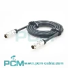
PCM-0885 uses two Molex 43025-0600 receptacle housings fitted with 43030-0001 female crimp terminals, connected by a 2m UL2464 20AWG×6C black PVC cable. The assembly has six circuits in two rows at a 3.00mm pitch, with 1:1 straight-through wiring. Its connector tails use LDPE inner molds and black PVC 45P MA-001 outer molds. The finished assembly is specified at up to 300VAC and 4A per contact for compatible power and general control-signal connections.
| Product Name | Micro-Fit 3.0 6-Pin Male to Female Extension Cable |
| Premier Cable P/N | PCM-0885 |
| Configuration | 6-Pin Male to 6-Pin Female, Straight-Through Extension |
| Cable Length | 2000 +30 mm |
| Cable Type | UL2464 |
| Wire Gauge | 20AWG × 6 Conductors |
| Cable OD | 6.0 mm |
Female-to-Female vs. True Male-to-Male Adapter
| Comparison | PCM-0885 Dual Female Harness | Male-to-Male Adapter |
|---|---|---|
| Interface | Receptacle-to-Receptacle | Plug-to-Plug |
| Mating target | Two compatible male connectors | Two compatible mother seats |
| Purpose | Module-to-module cable connection | Interface gender conversion or short-distance adapter |
| Applicability | Current BOM Correspondence | Need to redesign BOM |
Technical Knowledge

What is Micro-Fit 3.0 ?
Micro-Fit 3.0 is a compact multi-circuit electrical interconnect system developed by Molex,based on a 3.0omm centerline and available in wire-to-wire, wire-to-board, single-row and dual-rowconfigurations.
Its engineering value is the consolidation of multiple power or control-signal circuitsinto a relatively compact interface while providing detachable module connections through crimpterminals, polarization and mechanical locking.
The 3.0omm dimension refers to the center-to-center spacing of adjacent contacts, not the wire diameter, overall connector width or current rating.
What is 6-pin dual female cable harness ?
A female-to-female cable assembly is a preassembled cable with receptacle housings and female terminals at both ends.
PCM-0885 uses a 43025-0600 → 20AWG×6C cable → 43025-0600 architecture and is suitable for connecting two devices or modules equipped with compatible male interfaces.
Unlike a male-to-female extension cable, both ends have the same gender, so it cannot directly serve an existing connection that requires one male and one female end.

Pain Points
Product Details

PCM-0885
PCM-0885 integrates six circuits, a 2m routing distance, 20AWG conductors and dual-end overmold protection into one preassembled harness.
Compared with on-site loose-wire assembly, it reduces repeated crimping and pin-mapping work; compared with multiple separate connectors, it helps consolidate internal equipment wiring.
Its actual reliability should be demonstrated through crimp quality, continuity testing, insulation testing, temperature-rise evaluation and mechanical validation rather than relying solely on descriptions such as "original connector" or "high reliability."
Why can't 4A/contact be directly multiplied by 6?

Products Display

Similar products

Compatibility Statement
Compatibility Verification
Similar Micro-Fit 3.0 appearance does not mean that all connectors can mate directly. Both ends of PCM-0885 use 43025-0600 receptacle housings with 43030-0001 female terminals and therefore require compatible Micro-Fit 3.0 male mating interfaces.
Before selection, verify the exact Molex part number, circuit count, connector gender, housing type, terminal type, pitch, polarization, locking geometry, pin assignment, wire gauge, voltage, current and operating temperature. Compatibility cannot be determined solely from "6-pin, 3.00mm," and a dual-receptacle harness must not be treated as a male-to-male adapter.
Technical Compatibility Notice
Micro-Fit 3.0 is a physical electrical interconnect system rather than a CAN, RS485, USB or Ethernet protocol. PCM-0885 is a passive harness and contains no PHY, protocol converter, voltage converter, isolation circuit, signal amplifier or termination resistor.
It can carry power and general signals according to the equipment definition, but it does not automatically guarantee a particular high-speed protocol, differential impedance or communication distance.
How to Choose the Correct Product ?
Verify Gender and Exact Part Numbers
First, confirm that both equipment interfaces are compatible male interfaces capable of mating with the 43025-0600 receptacle, and verify the six circuits, dual-row configuration, 3.00mm pitch, polarization and locking geometry. If the equipment requires a connection between two receptacles, a true male-to-male solution should be selected; if an existing male-to-female harness must be extended, the corresponding extension architecture is required. Accurate interface definitions prevent the risk of purchasing a cable that cannot mate.
Verify Pinout and Circuit Allocation
Verify the six-circuit relationship between P1 and P2 and define the power, ground, control or signal function of every contact. For mixed power and signal wiring, check whether common grounding, isolation, shielding or special pin mapping is required. A 1:1 harness does not automatically correct an incorrect equipment pin assignment, so verification must be completed against the equipment's electrical drawings.
Calculate Current, Voltage Drop and Temperature Rise
Determine the current of each circuit, the number of simultaneously loaded circuits and the duty cycle according to the actual load, and include the supply and return resistance of the 2m cable in voltage-drop calculations. Applications approaching 4A per contact should undergo temperature-rise validation considering ambient temperature, cable bundling and heat dissipation. If load current is high or supply voltage is low, larger wire gauges, parallel power circuits or shorter cable lengths may be evaluated, but any modification requires renewed verification of terminal compatibility and current distribution.
Select Cable and Overmold for the Environment
Standard PCM-0885 is suitable for general fixed equipment wiring within its material and electrical limits. Applications involving continuous flexing, drag chains, oil, coolant, outdoor moisture, high temperature or severe vibration require appropriate high-flex, oil-resistant, temperature-resistant or sealed constructions supported by relevant testing. An ordinary PVC-overmolded harness must not automatically be considered waterproof, drag-chain-rated or automotive-grade.
Customization Capabilities
↕ Connector Architecture and Circuit Count
Customize circuit counts and female-to-female, male-to-female or male-to-male configurations. Exact housing, terminal, mating part numbers and polarization must be verified for compatibility.
□ Cable Length and Routing Dimensions
Custom lengths from 0.3m to 3m or project-specific dimensions are available. Define measurement references, tolerances and cable exits, and evaluate voltage drop, bending space and mounting requirements.
◉ Wire Gauge and Cable Construction
Select wire gauges, jackets, shielding or high-flex cables according to electrical and environmental requirements, with terminal compatibility, crimping processes and cable diameter verified.
⚙ Pinout and Conductor Color Customization
Customize straight-through or crossed pinouts and conductor colors. Define pin numbering, viewing orientation and signal assignments, then verify continuity, shorts and miswiring through testing.
⌘ Overmold, Strain Relief and Appearance
Customize molding materials, hardness, colors and cable-exit geometry to improve installation and strain relief. Waterproof, oil-resistant and high-flex performance requires dedicated design and validation.
◇ OEM Testing, Labeling and Packaging
Configure continuity, insulation, hi-pot, pull-force and temperature-rise testing. Custom part-number labels, barcodes, serial numbers and packaging support customer BOM integration and batch traceability.
Conclusion:
The correct product positioning of PCM-0885 is a Micro-Fit 3.0 six-circuit female-to-female power and signal cable assembly, not a male-to-male adapter. Through two Molex 43025-0600 receptacles, 43030-0001 female terminals, a 2m UL2464 20AWG×6C cable and dual-end overmolding, it provides standardized six-circuit connections for equipment with compatible male interfaces. Its core value lies in reducing on-site wiring, preserving defined pin mapping, consolidating power and general control circuits, and supporting modular wiring in OEM equipment.
Product FAQ
Can 2451320620 Directly Replace PCM-0885 ?
The two assemblies have closely related main constructions, including 2m length, six circuits, 20AWG wire and female-to-female overmolding, but these parameters alone do not establish complete interchangeability. Exact connectors, wiring, outer diameter, overmold dimensions, ratings and finished-assembly testing requirements must be verified
Does 300VAC Mean It Can Be Used in Every 300V System ?
No. Operating current, insulation requirements, transient overvoltage, environmental conditions, grounding and applicable safety standards must also be verified. The 300VAC value is the specified maximum voltage of the finished assembly, not proof of complete safety certification for every equipment type or regulatory application.
Does Dual-End Overmolding Mean Waterproof ?
No. Overmolding primarily provides mechanical protection and strain relief at the cable exits. IP65, IP67 or IP68 claims require a complete sealing design and corresponding ingress-protection test evidence.
How Can I Verify Compatibility with My Equipment ?
Provide the equipment mating part numbers, connector photos and drawings, six-circuit pin assignment, operating voltage, current per circuit, number of simultaneously loaded circuits, required length, ambient temperature and mounting method. Formal samples should undergo mechanical mating, continuity, insulation, voltage-drop, temperature-rise and equipment functional validation.