Micro-Fit 3.0 8-Pin Power and Signal Extension Cable: Features, Applications and Selection Guide
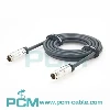
PCM-0879 is a 2m Micro-Fit 3.0 8-pin female-to-male extension cable using Molex 43025-0800 and 43020-0801 connectors with UL2464 20AWG×8C cable. Its 1:1 wiring supports industrial power and general signal extension.
What Does This Article Cover ?
Quick Product Introduction
PCM-0879 uses a Molex 43025-0800 eight-circuit Micro-Fit 3.0 receptaclehousing with 43030-0001 female terminals on one end and a Molex 43020-0801 eight-circuit Micro-Fit 3.0 plug housing with 43031-0001 male terminals on the other.
| Product Name | Molex Micro-Fit 3.0 8-Pin Male-to-Male Power andSignal Cable Assembly |
| Premier Cable P/N | PCM-0879 |
| Cable Length | 2000 + 30 mm |
| Cable Type | UL2464 |
| Wire Gauge | 20AWG x 8 Conductors |
| Outer Diameter | 6.5 mm |
43030-0001 vs 43031-0001
| Comparison | 43030-0001 | 43031-0001 |
|---|---|---|
| Terminal Type | Female Crimp Terminal | Male Crimp Terminal |
| Contact | Female | Male |
| Wire Gauge | 20,22,24AWG | 20,22,24AWG |
| Max. Insulation OD | 1.85mm | 1.85mm |

What Is a Micro-Fit 3.0 Extension Cable?
A Micro-Fit 3.0 extension cable adds a compatible connection section, typically with a plug-to-receptacle configuration, to increase the distance between equipment.
PCM-0879 can address insufficient cable length, equipment relocation or inter-module routing within control cabinets while preserving the original connector architecture. The extension does not change the connector standard or provide voltage or communication-protocol conversion. Before integration, verify the mating part numbers, polarization, pinout, wire gauge and electrical ratings at both ends.
Engineers should also evaluate voltage drop, temperature rise and signal integrity resulting from the additional cable length.
Why Is a Male-to-Female Architecture Suitable for Extension?
A male-to-female architecture is suitable for extending an existing connection because one end mates with the original cable or equipment interface, while the opposite end provides the corresponding mating interface at a greater distance.
Unlike female-to-female assemblies, which commonly connect two compatible male interfaces, a male-to-female extension can preserve the original connector architecture while increasing routing flexibility. PCM-0879 is suitable for inter-module connections in control cabinets, robotics and test equipment.
However, both connector genders, mating part numbers, pinout and electrical ratings must be verified, together with voltage drop, temperature rise and signal integrity after extension.

Pain Points
When PCB, controller, power-supply or I/O module positions change, the original harness may no longer be long enough.
PCM-0879 adds 2m of routing distance while preserving a compatible Micro-Fit interface and straight-through wiring architecture.
Temporary solder joints or loose wire splices introduce additional connection points and increase wiring, insulation and maintenance complexity.
A preassembled Micro-Fit extension cable standardizes crimping, pin mapping and strain relief during manufacturing.
Manually extending eight conductors creates significant pin-mapping risk.
A predefined 1:1 cable architecture simplifies manufacturing inspection and reduces wiring errors.
An extension cable increases resistance, voltage drop, signal-path length and EMI exposure.
The 20AWG conductors help limit resistance, but the complete channel should still be evaluated in the intended system.
Product Details

PCM-0879
Micro-Fit 3.0 8-Circuit Power and Signal Extension Cable
PCM-0879 features a Molex Micro-Fit 3.0 male-to-female configuration. P1 combines the 43025-0800 eight-circuit receptacle housing with 43030-0001 female terminals, while P2 uses the 43020-0801 plug housing with 43031-0001 male terminals.
LDPE inner molding and black PVC 45P overmolding reinforce both cable exits. The assembly uses UL2464 20AWG×8C black PVC cable with a 6.5mm outer diameter and a 2000±30mm length, supporting power and signal extension in industrial equipment.
Why Is a Male-to-Female Architecture Suitable for Extension?
A male-to-female architecture extends an existing connection while preserving the original mating relationship. One end connects to the existing cable or equipment interface, while the opposite end provides the corresponding interface at a greater distance, allowing the connection path to continue.
Compared with female-to-female assemblies, which commonly link two compatible male interfaces, this configuration is particularly useful when the original cable is too short, equipment is relocated or routing between control-cabinet modules is required.
PCM-0879 uses a Micro-Fit 3.0 male-to-female design. Before extension, verify mating part numbers, polarization, pinout and electrical ratings, and evaluate voltage drop, temperature rise and signal integrity.

Products Display

Similar products

Compatibility Statement
Compatibility Verification
PCM-0879 uses a Micro-Fit 3.0 male-to-female configuration: the 43025-0800 receptacle housing with 43030-0001 female terminals, and the 43020-0801 plug housing with 43031-0001 male terminals.
Verify mating part numbers, polarization, locking geometry, wire gauge and electrical ratings before integration. Eight-circuit straight-through wiring establishes corresponding pin continuity only; power, ground and signal assignments must follow the equipment wiring diagram.
Technical Compatibility Notice
PCM-0879 is a passive extension cable and does not provide protocol, voltage or signal conversion. Adding 2m of cable requires renewed evaluation of circuit resistance, voltage drop, temperature rise and signal integrity, particularly when multiple contacts carry current simultaneously.
The finished assembly is specified at 300VAC and 3.5A per contact; the individual terminal's 7A rating must not be applied directly. UL2464 cable identification does not establish independent UL Listed certification for the complete overmolded assembly.
How to Choose the Correct Product ?
Verify Connector Gender and Exact Part Numbers
Connector gender is one of the most important extension-cable selection criteria.
PCM-0879 uses a 43025-0800 receptacle on one side and a 43020-0801 plug on the other.
The existing equipment and cable interfaces must be verified against these exact part numbers rather than relying only on the description "Micro-Fit 8-pin."
Verify Pin Assignment and 1:1 Extension Mapping
The extension preserves the original electrical relationship only when the system pinout matches the PCM-0879 straight-through mapping.
A complete Pin 1-to-Pin 8 wire table should be documented, especially when power, ground and control circuits share the same connector.
Select According to Total Length, Current and Voltage Drop
Selection should consider the combined length of the original cable plus the 2m extension.
Low-voltage higher-current systems should be checked for DC resistance, voltage drop and temperature rise across the complete connection path.
Select Cable Construction for the Environment
Standard PCM-0879 uses UL2464 PVC cable for general fixed equipment wiring.
Continuous-flex robotics, drag chains, oil exposure, outdoor use, high temperature or severe vibration require separately validated cable and mechanical constructions.
Customization Capabilities
↕ Micro-Fit Interface and Circuit-Count Customization
Different Micro-Fit 3.0 housings, circuit counts and plug/receptacle combinations can be developed according to the target equipment. Exact housing and terminal part numbers should be used for compatibility verification.
□ Cable Length Customization
Custom extension lengths can be produced according to equipment layout, while longer versions require renewed evaluation of voltage drop, resistance, signal integrity and mechanical routing.
◉ Wire Gauge and Cable Customization
Different wire gauges and cable constructions can be selected according to current, voltage drop, flexibility and equipment space, with corresponding terminal and crimp requirements revalidated.
⚙ Pinout and Wiring Customization
Standard PCM-0879 uses 1:1 wiring, while customized pin mappings can be developed from OEM electrical drawings with clearly defined connector views, pin numbers, wire colors and signal names.
⌘ Overmold and Strain-Relief Customization
Inner molds, outer molds, cable-exit geometry, strain-relief length, material hardness and color can be customized according to equipment and mechanical requirements.
◇ OEM Testing, Labeling and Packaging
OEM programs can incorporate continuity, short-circuit, insulation, hi-pot, contact-resistance, voltage-drop, pull and temperature-rise testing together with customized labels, barcodes, serial numbers, logos and packaging.
Product FAQ
Is 43025-0800 Male or Female ?
Molex officially identifies 43025-0800 as a receptacle housing, while 43030-0001 is a female terminal. The assembled interface should therefore be treated as the female/receptacle side.
What Is the Correct Gender Configuration ?
The exact connector combination should be described as Receptacle-to-Plug or Female-to-Male.
Does PCM-0879 Have a Fixed Transmission Direction ?
The cable itself is passive and non-directional electronically, but actual power-source, load and signal direction must follow the equipment design.
What Is the Maximum Voltage ?
The finished PCM-0879 assembly is specified at 300VAC maximum.
Does the 2m Extension Cause Voltage Drop ?
Yes. Adding 2m increases total conductor resistance, and actual voltage drop depends on load current, total system length and conductor resistance.