HSD 4Pin Z Code to RJ45 Female Panel Mount Cable: Features, Applications and Selection Guide
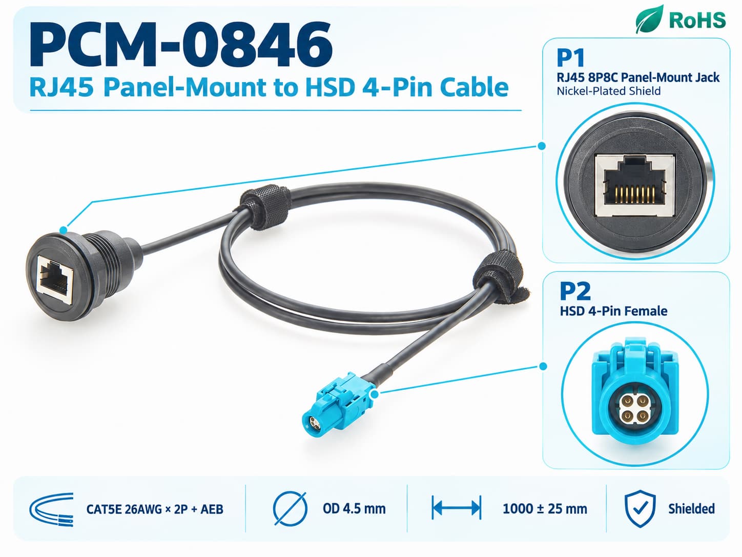
PCM-0846 is an HSD 4Pin Z Code female to RJ45 8P8C female circular panel-mount high-speed data cable using Cat5e 26AWG×2P+AEB shielded cable. The standard version is 1m long with an approximately 4.5mm OD, while the RJ45 side features a nickel-plated metal housing and 26mm panel cutout. It extends an internal HSD high-speed interface to a dashboard, test panel or equipment enclosure for automotive networking, infotainment, ECU testing, Ethernet diagnostics and laboratory access. Actual 100/1000Mbps communication capability must be verified according to pinout, PHY and the target Ethernet standard.
What Does This Article Cover ?
Modern vehicles and automotive electronic test systems are integrating an increasing number of high-speed data interfaces. HSD connectors are widely used in automotive cameras, infotainment, displays, data modules and other high-speed electronic systems because of their compact size, 100Ω impedance-controlled architecture, shielding, mechanical coding and reliable locking capability.
However, an HSD interface inside a vehicle or electronic module is not always convenient for direct connection to laboratory computers, network-analysis equipment, diagnostic instruments or standard RJ45 patch cables.
In ECU bench testing, HIL systems, automotive diagnostic equipment, development prototypes, in-vehicle computers and production test fixtures in particular, engineers often need to extend an internal HSD connection point to an enclosure or control panel for easier connection, maintenance and testing.
PCM-0846 is an HSD 4Pin Z Code Female to RJ45 Female Panel Mount Cable developed specifically for this requirement.
This article systematically explains HSD interfaces, RJ45 8P8C interfaces, Cat5e cabling, panel-mount architecture and the differences between Automotive Ethernet and conventional RJ45 Ethernet. It also analyzes the application value, selection risks, technical compatibility and customization capabilities of PCM-0846.
Quick Product Introduction
PCM-0846 features an HSD 4Pin Z Code female connector at one end and an RJ45 8P8C female circular panel-mount interface at the other.
The assembly uses Cat5e 26AWG×2P+AEB shielded data cable with a standard length of 1000±25mm, an approximate cable OD of 4.5mm and a black PVC outer jacket.
The RJ45 side uses a nickel-plated metal housing with an approximately 26mm circular panel cutout, allowing installation on dashboards, control panels, test boxes, equipment enclosures or laboratory test fixtures.
| Product Name | RJ45 8P8C Panel-Mount Jack to HSD 4-Pin Female Cable |
| Premier Cable P/N | PCM-0846 |
| P1 Interface | Shielded RJ45 8P8C jack with panel-mount structure |
| P2 Interface | HSD 4-Pin Female |
| Connection Type | RJ45 Jack to HSD 4-Pin Female |
| Cable Type | CAT5E, 26AWG x 2P + AEB |
| Cable Outer Diameter | 4.5mm |
| Product Length | 1000 + 25mm |
Unlike a simple HSD-to-RJ45 patch cable, the primary value of this product is not merely connector-form conversion. More importantly, it provides a fixed, serviceable and repeatedly accessible external RJ45 connection point.
It is especially suitable for automotive network testing, ECU benches, HIL systems, infotainment equipment, in-vehicle computers, gateways and development test platforms.

What Is an HSD 4Pin Z Code Interface ?
HSD, meaning High-Speed Data, is a 100Ω impedance-controlled interconnection system widely used in automotive electronics. It incorporates full shielding, mechanical coding and a secure locking structure. A standard 4Pin interface contains four signal contacts, typically arranged as two differential pairs.
Z Code identifies the mechanical keying configuration used to reduce incorrect mating with incompatible interfaces. HSD defines the connector family and physical transmission architecture rather than a specific communication protocol.
Depending on the OEM system design, the same HSD connector family may carry Ethernet, LVDS, USB or other high-speed signals. Pinout and protocol compatibility must therefore be verified separately.
What Is a Circular RJ45 Panel-Mount Interface ?
A circular RJ45 panel-mount interface uses an external mounting structure to secure an RJ45 female connector to a metal panel, plastic enclosure, control box or dashboard.
PCM-0846 fits an approximately 26mm circular panel cutout. After installation, the RJ45 port remains accessible outside the equipment, while the internal 1m cable connects to the HSD interface.
This creates a convenient external service connection without requiring direct access to the internal ECU or controller connector, improving interface management during testing, debugging, equipment replacement and routine maintenance.

Pain Points
HSD-to-RJ45 Passive Cable vs. Active Media Converter
| Item | PCM-0846 Passive Cable | Active Media Converter |
| Connector Transition | HSD to RJ45 | HSD/T1 to RJ45 |
| Active Electronics | No | Yes |
| PHY Conversion | No | Possible |
| Protocol Conversion | No | Depending on device |
| Panel Breakout | Excellent | Device-dependent |
| Power Consumption | None | Requires power |
| Main Purpose | Pin Mapping,Extension,Testing | PHY/Media Conversion |
Products Display
Similar products
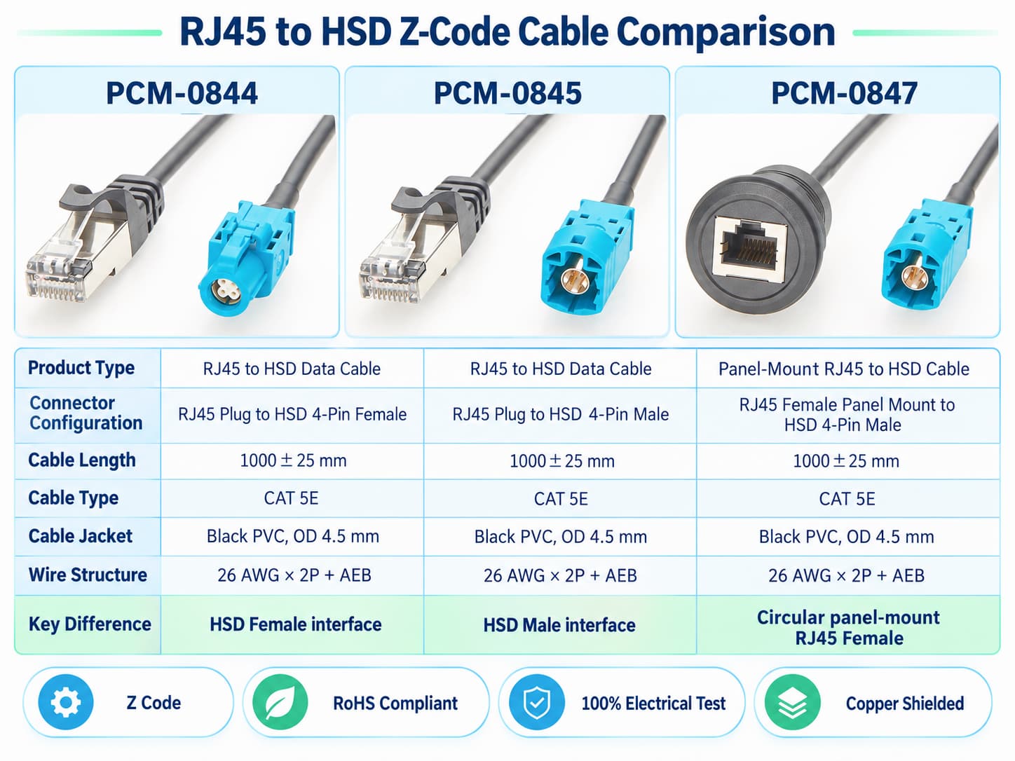
Compatibility Statement
Compatibility Verification
PCM-0846 provides physical interconnection and pin mapping between an HSD 4Pin Z Code interface and an RJ45 8P8C female interface.
It is a passive cable assembly, not an Automotive Ethernet media converter. Selection requires verification of the complete connector part numbers, gender, coding, mechanical keying, pin assignments, differential-pair mapping, shielding, grounding, PHY types, Ethernet standards and data rates at both ends.
Physical connection alone does not guarantee communication. If the connected devices use incompatible PHY technologies, such as 1000BASE-T1 and 1000BASE-T, PCM-0846 cannot perform the required protocol or physical-layer conversion.
Technical Compatibility Notice
PCM-0846 uses a Cat5e 26AWG×2P+AEB cable containing two differential pairs plus shielding. Standard 100BASE-TX uses two pairs, whereas standard 1000BASE-T over RJ45 requires four twisted pairs. Although 1000BASE-T1 uses only one pair, it requires a dedicated 1000BASE-T1 PHY.
Therefore, combining Cat5e cable with an RJ45 connector does not automatically provide standard Gigabit Ethernet, and an HSD-to-RJ45 cable does not convert Automotive Ethernet into conventional Ethernet.
Connecting a 100BASE-T1 or 1000BASE-T1 ECU to a standard PC or switch generally requires an active media converter, test adapter or gateway with compatible PHY conversion.
Product Comparison and How to Select the Right Cable ?
Identify the Ethernet PHY Used by the Equipment
First identify the PHY technology used by both devices. A passive cable may be suitable when the differential signals are compatible and only physical-interface transition and pin mapping are required. If the connection involves conversion between 100BASE-T1/1000BASE-T1 and conventional 100BASE-TX/1000BASE-T, an appropriate active PHY converter is required.
Confirm the Complete HSD-to-RJ45 Pin Assignment
Define the complete mapping between the four HSD signal contacts and eight RJ45 contacts, including differential-pair allocation, unused pins and shield termination. Incorrect pin or pair mapping may prevent link establishment, reverse signal polarity, interrupt shielding continuity or degrade signal integrity. A verified pinout and wiring table should therefore be provided before production.
Verify Panel-Mount Dimensions
In addition to the approximately 26mm circular cutout, verify panel thickness, mounting nut or locking structure, front and rear clearance, RJ45 mating space and the internal cable bend radius. These dimensions must be evaluated together to prevent installation interference, insecure mounting, connector-access problems or excessive cable bending inside the enclosure.
Verify Performance by Data Rate and Cable Architecture
Do not determine communication capability from the Cat5e designation alone. PCM-0846 uses a two-pair cable architecture, so compatibility must be evaluated according to pair count, pinout, PHY and target data rate. Standard 1000BASE-T normally requires four twisted pairs and is therefore not directly supported by a two-pair passive cable configuration.
Customization Capabilities
↕ Cable Length Customization
Cable length can be customized for equipment spacing and routing. Longer versions require renewed validation of insertion loss, return loss, crosstalk and link margin.
□ HSD Gender and Coding Customization
HSD gender and coding can be customized for the device mating interface. The complete device-side connector part number must be confirmed before production.
◉ RJ45 Panel-Mount Customization
Mounting method, panel thickness and locking structure can be customized. An enclosure drawing should be provided to verify the panel cutout and installation dimensions.
⚙ inout and Pair Mapping Customization
HSD-to-RJ45 pinout and differential-pair mapping can be customized. A complete wiring table must be provided and verified before production.
⌘ Cable Type and Shield Customization
Wire gauge, pair count, shielding and jacket can be customized for protocol and EMC requirements. Standard 1000BASE-T applications require evaluation of a four-pair architecture.
◇ Jacket, Overmold and Label Customization
Jackets, overmolding, heat-shrink and labels can be customized, with temperature, abrasion, flame-retardant and low-smoke requirements defined for the application environment.
Product FAQ
Can PCM-0846 Connect Directly to a Standard PC RJ45 Port ?
Only when the HSD-side equipment uses signals compatible with the PC-side RJ45 PHY, pinout and Ethernet standard.
If the HSD side uses 100BASE-T1 or 1000BASE-T1 while the PC uses 100BASE-TX or 1000BASE-T, a media converter is generally required for PHY conversion.
PCM-0846 does not perform this conversion.
Does an HSD Interface Always Mean Automotive Ethernet ?
No.
HSD is a high-speed physical interconnection system that can be used for Ethernet, LVDS, USB and other high-speed differential applications.
The actual protocol carried by the connector must be determined from the equipment design.
Why Does the RJ45 Have 8 Pins While the Cable Contains Only 2 Pairs ?
An RJ45 8P8C connector provides eight contacts, but not every application must use all eight contacts.
The specific RJ45 pins used in PCM-0846 depend on the mapping between the four HSD contacts and the target equipment definition.
Unused contacts may remain NC according to the design.
Is the 26mm Cutout Suitable for Every Panel ?
The cutout diameter alone is not sufficient.
Panel thickness, mounting hardware, nut position, RJ45 plug clearance and internal cable space must also be considered.
A complete mechanical drawing should be confirmed before mass-producing the panel.
Can Different Cable Lengths Be Customized ?
Yes.
Lengths such as 0.3m, 0.5m, 1.5m, 2m or other customized values can be produced according to the equipment layout.
For high-speed data applications, signal integrity and target communication-standard requirements should be reverified when cable length increases.
Can Other HSD Codings Be Customized ?
Other codings can be evaluated according to the actual connector P/N.
However, coding directly affects mechanical mateability, so customers should provide the complete device-side part number rather than relying only on interface photographs or color.