Micro-Fit 3.0 4-Pin 90° Right-Angle Power and Signal Cable: Features, Applications and Selection Guide
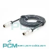
PCM-HD-0212 is a 1.5m Micro-Fit 3.0 4-pin 90° right-exit power and signal cable using a dual-row 2×2, 3.00mm interface and UL2464 20AWG×4C black PVC cable. The opposite end provides four color-coded wires stripped 25±5mm and tinned 4±1mm. An LDPE inner mold, UV sealing adhesive and PVC outer mold protect the connector exit. The finished assembly is specified at 300V AC/DC, 5A per pin and -40°C to +105°C for industrial controllers, robotics, embedded equipment, power modules and OEM internal wiring.
What Does This Article Cover?
This article introduces the PCM-HD-0212 Micro-Fit 3.0 four-circuit, 90° right-side power and signal cable assembly. It explains cable-exit clearance in compact equipment, the 2×2 connector configuration, 20AWG cable construction and tinned open-end integration. It also distinguishes a right-angle cable exit from a PCB right-angle header, discusses the 5A-per-pin rating and voltage-drop considerations for the 1.5m cable, and provides compatibility and selection guidance for industrial controllers, robotics and embedded equipment.
Quick Product Introduction
PCM-HD-0212 is main engineering value is not merely connecting a Micro-Fit interface to four open wires, but redirecting the cable path through a 90° side exit to reduce longitudinal clearance behind the connector.
| Product Name | HSG 3.0 4-Pin Right-Angle Plug to Open-End Cable Assembly |
| Premier Cable P/N | PCM-HD-0212 |
| Pitch | 3.0 mm |
| Cable Length | 1500 ± 30 mm |
| Cable Standard | UL2464 |
| Conductor | 20AWG × 4C |
| Outer Diameter | 5.5 ± 0.15 mm |
90° Right-Exit PCM-HD-0212 vs Straight-Exit Cable
| Comparison | 90° Right-Exit PCM-HD-0212 | Straight-Exit Cable |
|---|---|---|
| Cable Direction | Sideways | Rearward |
| Tight Enclosures | Better suited | May require more depth |
| Cable Bend at Connector | Reduced | May require immediate bend |
| Best Use | Compact equipment | General wiring |

What Is a 4-Pin 2×2 Dual-Row Configuration?
PCM-HD-0212 uses a 2×2 arrangement with two circuits in each of two rows for a total of four circuits.
Compared with a four-circuit single-row layout, a 2×2 configuration reduces interface width and is particularly suitable for compact PCBs, controllers, power modules and embedded equipment.
Molex's official 43025 family includes a dual-row four-circuit Micro-Fit 3.0 receptacle housing with a 3.00mm pitch, confirming the 2×2 four-circuit architecture as part of the Micro-Fit system.
What Is a 90° Right-Side Cable Exit ?
The 90° right-angle description of PCM-HD-0212 primarily refers to cable-exit direction.
In a conventional straight-exit cable, the cable extends axially behind the connector. PCM-HD-0212 redirects the cable path by approximately 90 degrees so that the cable exits toward the right side of the connector.
The engineering benefits include reduced rear clearance, less need for an immediate sharp cable bend, improved internal routing and reduced interference with housings, PCBs or adjacent modules.
A 90° cable exit must be distinguished from a right-angle PCB header.
Molex officially treats right-angle and vertical headers as different component categories from wire-side receptacle and plug housings.
PCM-HD-0212 should therefore be described as a cable assembly with a 90° right-side cable exit rather than automatically identified as a PCB right-angle header.

Pain Points
The 25±5mm individual wire length and 4±1mm tinned ends support consistent soldering and secondary termination.

Product Details
PCM-HD-0212
PCM-HD-0212 features a Micro-Fit 3.0 four-circuit, dual-row 2×2 interface with 3.00mm pitch and a 90° right-side cable exit for compact equipment routing.
Tin-plated phosphor-bronze terminals are protected by UV adhesive, an LDPE inner mold and a black 50P PVC outer mold. The assembly uses UL2464 20AWG×4C black PVC cable with a 5.5±0.15mm outer diameter and a 1500±30mm length.
P2 provides red, black, yellow and white open-ended conductors, with 25±5mm individual wire lengths and 4±1mm tinned ends for downstream soldering or termination. The exact Molex terminal part number must be confirmed against the approved BOM.
Manufacturing and Testing Priorities
PCM-HD-0212 manufacturing quality depends on controlled wire cutting, stripping, crimping, terminal insertion, pin mapping, UV adhesive application, inner and outer overmolding, and open-end tinning. The 90° bend region must maintain appropriate conductor positioning and bend radius to avoid excessive compression and internal stress concentration.
Depending on application requirements, finished-assembly validation may include continuity, short-circuit, miswire, insulation, hi-pot, contact-resistance, voltage-drop, pull-force and temperature-rise testing, with clearly defined acceptance criteria.

Products Display

Similar products

Compatibility Statement
Compatibility Verification
Similar Micro-Fit 3.0 connectors are not necessarily interchangeable. PCM-HD-0212 selection requires verification of exact housing and terminal part numbers, mating interface, 2×2 configuration, polarization, locking geometry, cable-exit direction, pinout and electrical ratings.
The supplied information does not identify the exact P1 Molex part numbers, so universal compatibility with all four-pin devices should not be claimed. Conductor colors are identification aids; actual power, ground and signal functions must follow the equipment wiring diagram.
Technical Compatibility Notice
PCM-HD-0212 is a passive power and general signal cable, not a protocol, voltage or signal converter. CAN, RS485, USB and similar applications require separate verification of pair construction, impedance, shielding, termination and signal integrity; UL2464 alone does not establish high-speed compatibility.
The finished-assembly design rating is 5A per pin. Actual current capacity depends on wire gauge, contact resistance, simultaneous loading, ambient temperature and heat dissipation. Four contacts do not automatically provide a 20A harness rating; current derating and temperature-rise validation are required.
How to Choose the Correct Product ?
Verify the Micro-Fit Interface, Pinout and Exact Part Numbers
First verify that the equipment uses a compatible Micro-Fit 3.0 four-circuit, 2×2 dual-row, 3.00mm interface.
Then confirm the exact housing and terminal part numbers, gender, polarization, locking geometry and pin assignment.
Compatibility must not be determined from the description "Micro-Fit 4-pin" alone.
The relationship between the red, black, yellow and white conductors and each P1 circuit should also be clearly documented.
Verify the 90° Right-Exit Orientation
Before ordering a 90° cable, define the connector mating-face orientation, cable-exit direction, PCB position and enclosure clearance.
The drawing must clearly establish the viewing direction used to define "right."
For space-sensitive projects, the connector, cable exit, nearby PCB and enclosure wall should be shown together in the mechanical drawing.
This prevents a situation in which the electrical connector is correct but the cable exits in the wrong direction for the equipment.
Select According to Current, Length and Voltage Drop
PCM-HD-0212 uses 20AWG conductors, a 1.5m length and a 5A-per-pin finished rating.
System selection should verify current per circuit, the number of simultaneously loaded pins, supply voltage, round-trip length, voltage drop and ambient temperature.
Load-end voltage is particularly important in 5V and 12V higher-current systems.
Applications operating continuously near 5A per pin should also undergo temperature-rise validation.
Select the Open-End Preparation for the Final Termination
If P2 is intended for PCB soldering, the 4±1mm tinned end provides convenient preparation.
If P2 will be terminated into a crimp, screw or spring terminal, the target terminal manufacturer's requirements for tinned wire, bare wire or ferrules should be followed.
OEM versions can customize strip length, tin length, ferrules, secondary terminals and other open-end preparation according to the final termination method.
Customization Capabilities
↕ Interface and Circuit Count
Customize 2-, 4-, 6- and 8-circuit configurations, with compatibility verified through exact part numbers, mating interfaces and polarization.
□ Cable-Exit Direction
Customize 90° left, right or straight cable exits according to equipment drawings and defined mating-face orientation.
◉ Cable Length and Wire Gauge
Customize cable length and wire gauge, with renewed verification of terminal compatibility, crimping, voltage drop and current capacity.
⚙ Pinout and Conductor Colors
Customize pin assignments, conductor colors and power or signal distribution according to approved equipment wiring diagrams.
⌘ Open-End Termination
Choose bare, tinned, ferrule, crimp-terminal or secondary-connector ends, with strip and free-wire lengths tailored to termination requirements.
◇ Overmolding, Testing and OEM Traceability
Customize overmolding, strain relief, labels and packaging, with electrical and mechanical testing and batch traceability for OEM production.
Product FAQ
What Does 90° Right-Angle Mean ?
It means that the cable is molded to exit approximately 90 degrees toward the side of the connector.
The viewing orientation must be defined on the engineering drawing because "right" can otherwise be interpreted differently.
Does Four 5A Pins Mean a 20A Cable ?
No. Simultaneous loading creates cumulative heat in the connector and cable, so current derating and temperature-rise validation are required.
Why Are the P2 Conductors Tinned ?
Tinning facilitates PCB or wire soldering and helps prevent the stranded conductors from fraying.
Do Red, Black, Yellow and White Have Fixed Functions ?
No universal electrical function should be inferred from conductor color alone.
Power, ground and signal assignments must follow the approved PCM-HD-0212 pinout and wire table.
Does Multi-Layer Overmolding Allow Unlimited Flexing ?
No. Overmolding reduces stress at the cable exit, but continuous high-frequency flexing requires dedicated continuous-flex cable and flex-life validation.