Micro-Fit 3.0 4-Pin 45° Right-Exit Power and Signal Cable: Features, Applications and Selection Guide
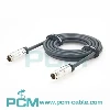
PCM-HD-0220 is a 1.5m Micro-Fit 3.0 4-pin 45° right-exit power and signal cable using a 3.00mm dual-row 2×2 interface, UL2464 20AWG×4C black PVC cable and four tinned open-ended conductors. Its 45° molded routing balances rear and side clearance, while an LDPE inner mold, UV adhesive and PVC outer mold provide cable-exit support and strain relief. The finished assembly is specified at 300V AC/DC, 5A per pin and -40°C to +105°C for industrial controllers, robotics, IoT gateways, embedded equipment and power-control modules.
What Does This Article Cover?
This article introduces the PCM-HD-0220 Micro-Fit 3.0 four-circuit, 45° right-exit cable assembly. It explains compact routing, the 2×2 interface, 20AWG cable and tinned open ends, along with 5A-per-pin rating considerations, voltage drop and OEM compatibility.
Quick Product Introduction
PCM-HD-0220 uses a Micro-Fit 3.0 four-circuit, 2×2 dual-row interface with a 3.00mm pitch and a 45° right-side cable exit.
| Wire length | HSG 3.0 4-Pin 45° Right-Angle Plug to Open-End Cable Assembly |
| Premier Cable P/N | PCM-HD-0220 |
| Connector Configuration | 4-Pin HSG 3.0 Plug to 4-Core Open End |
| Cable Length | 1500 + 30 mm |
| Connector P1 | HSG 3.0 4-Pin 45° Right-Angle Plug |
| Connector P2 | 4-Core Open End |
| Cable OD | 5.5 ± 0.15 mm |
45°Right Exit vs. 90° Right Exit
| Comparison | 45°Right Exit | 90° Right Exit |
|---|---|---|
| Direction | Diagonal | Sideways |
| Rear Space | Medium | Lowest |
| Side Space | Medium | Higher |
| Direction Change | Moderate | Strong |
Technical Knowledge

What Is Micro-Fit 3.0 ?
Micro-Fit 3.0 is a compact multi-circuit power and signal interconnect architecture based on a 3.00mm centerline.
Molex's official 43025 family includes dual-row configurations with two, four, six, eight and additional circuit counts.
For example, Molex identifies 43025-0400 as a four-circuit, dual-row, 3.00mm Micro-Fit 3.0 receptacle housing with polarization, mating lock and an operating-temperature range of -40°C to +105°C.
For equipment designers, this type of interface provides compact packaging, multiple circuits, crimp termination, polarization, mechanical locking and detachable serviceability.
What Is a 2×2 Dual-Row Four-Circuit Layout ?
PCM-HD-0220 uses two circuits in each of two rows, creating a 2×2 four-circuit configuration.
Compared with a four-circuit single-row connector, the 2×2 arrangement consolidates four electrical paths into a shorter horizontal package.
This makes it particularly suitable for compact controllers, power boards, embedded PCBs, IoT gateways and robotic control modules.
Molex's official 43025 family also includes a four-circuit dual-row configuration, confirming 2×2 as an established Micro-Fit 3.0 mechanical architecture.

Pain Points

Product Details
PCM-HD-0220
PCM-HD-0220 features a Micro-Fit 3.0 four-circuit, dual-row 2×2 interface with 3.00mm pitch and a 45° right-side cable exit. Tin-plated phosphor-bronze contacts are protected by UV adhesive, an LDPE inner mold and a black 50P PVC outer mold.
The assembly uses UL2464 20AWG×4C black PVC cable, with a 5.5±0.15mm outer diameter and 1500±30mm length. P2 provides red, black, yellow and white open-ended conductors, with 25±5mm free-wire lengths and 4±1mm tinned ends for secondary termination.
Exact housing and terminal part numbers must follow the approved BOM.
Manufacturing Process
The PCM-HD-0220 manufacturing process includes cable cutting, jacket processing, conductor stripping, terminal crimping, terminal insertion, pin mapping, 45° pre-molding, UV adhesive application, PVC outer overmolding, P2 stripping, P2 tinning and electrical inspection.
For the 45° construction, quality involves more than the visible outer angle.
Internal conductors must maintain an appropriate bend radius, position, compression level and strain distribution through the angled transition.
If internal wires are excessively compressed during molding, the external appearance may be correct while long-term mechanical reliability is still reduced.

Products Display

Similar products

Compatibility Statement
Compatibility Verification
PCM-HD-0220 uses a Micro-Fit 3.0 four-circuit interface, but matching appearance, circuit count and pitch do not guarantee compatibility. The exact P1 housing and terminal part numbers are not provided, so universal compatibility must not be claimed.
Verify the mating interface, polarization, locking geometry, cable-exit orientation, pinout and electrical ratings. Conductor colors are identification aids; actual electrical functions must follow the approved equipment drawing.
Technical Compatibility Notice
PCM-HD-0220 is a passive power and general signal cable, not a protocol or voltage converter. CAN, RS485, USB and similar applications require separate verification of pair construction, impedance, shielding and signal integrity; UL2464 alone does not establish high-speed compatibility.
The finished-assembly rating is 5A per pin. Actual current capacity depends on wire gauge, contact resistance, simultaneous loading and heat dissipation. Four contacts do not automatically provide a 20A harness rating; derating and temperature-rise validation are required.
How to Choose the Correct Product ?
Verify the Micro-Fit Interface and Complete Pinout
Verify the exact housing, terminal and mating part numbers, connector gender, 2×2 configuration, polarization and locking geometry. The approved drawing must define the relationship between all four pins, conductor colors and electrical functions. "Micro-Fit 4-pin" alone is insufficient to establish compatibility.
Verify the 45° Right-Exit Direction and Mechanical Space
Confirm the 45° right-exit direction using the mating-face orientation, PCB position and enclosure layout, preferably with 2D or 3D assembly drawings. Check clearance around screws, heat sinks, fans and neighboring modules, and maintain an appropriate cable bend radius to prevent installation interference.
Select According to Current, Length and Voltage Drop
PCM-HD-0220 uses 20AWG conductors, a 1.5m cable and a finished-assembly rating of 5A per pin. Evaluate circuit voltage drop using actual current, simultaneous loading, supply voltage and ambient temperature. Load-end voltage is especially important in 5V and 12V systems, while sustained high-current operation requires temperature-rise validation.
Select Open-End Preparation According to Final Termination
The standard 4±1mm tinned ends are suitable for PCB soldering when specified by the assembly process. For crimp, screw or spring-clamp terminals, select bare wire, ferrules or other preparation according to the terminal manufacturer's requirements. Verify strip length and avoid assuming that tinning is suitable for every termination method.
Customization Capabilities
↕ Connector and Circuit-Count Customization
Customize 2-, 4-, 6- and 8-circuit configurations, verifying exact part numbers, mating interfaces, polarization and pinout against the customer BOM.
□ Cable-Exit Angle and Direction
Customize 45°, 90° left/right or straight exits according to PCB position, enclosure geometry and cable-routing requirements.
◉ Cable Length and Wire Gauge
Customize cable length and wire gauge, with renewed verification of terminal compatibility, crimping, voltage drop and finished-assembly current capacity.
⚙ Pinout and Wire-Color Customization
Customize pinout, conductor colors and power or signal assignments, with circuit identification through numbering, heat-shrink markers or labels.
⌘ P2 Termination Customization
Choose bare, tinned, ferrule or secondary-connector terminations, with strip and free-wire lengths tailored to the final connection method.
◇ Overmolding, Materials, Testing and Labeling
Customize molding materials, hardness, colors and labels, with electrical, mechanical and environmental testing configured to project requirements.
Product FAQ
What Is the Main Benefit of a 45° Right Exit ?
It provides an intermediate geometry between straight and 90° exits, using both rear and side space and allowing a more natural diagonal cable path.
Is 45° Better Than 90° ?
No. A 90° exit may be better when rear clearance is extremely limited, while a 45° exit can be more suitable when both rear and side space are available. They address different mechanical layouts.
Why Is P2 Tinned ?
Tinning primarily reduces strand fraying, simplifies PCB soldering and improves manual assembly consistency.
Can a 45° Left-Exit Version Be Customized ?
Yes. Left and right orientation must be defined using an approved mating-face reference view.
How Do I Confirm PCM-HD-0220 Compatibility ?
Customers should provide the mating connector part number, P1 mechanical drawing, Pin 1-to-Pin 4 assignments, required 45° viewing direction, operating voltage, current per circuit, number of loaded circuits, ambient temperature, P2 termination method and available installation space.
Sample validation should include mechanical mating, cable-exit clearance, continuity, pin mapping, insulation, voltage drop, temperature rise, pull force and equipment functional testing.