Right-Angle HSD 4+2 Pin Z Code Automotive Extension Cable: Features, Applications and Selection Guide
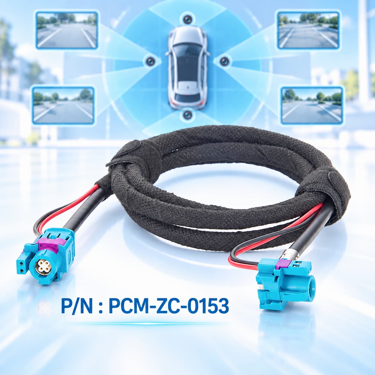
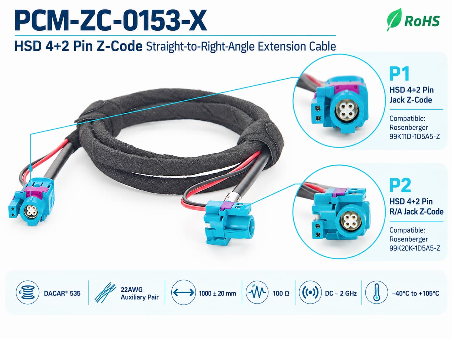
PCM-ZC-0153 is an HSD 4+2 Pin Z Code extension cable for automotive high-speed electronic systems. P1 uses a straight jack compatible with Rosenberger 99K11D-1D5A5-Z, while P2 uses a 90° right-angle jack compatible with 99K20K-1D5A5-Z. Its four high-speed signal pins and two auxiliary circuit pins combine high-speed data and auxiliary circuits in one interface. Featuring Dacar 535, 100Ω nominal impedance and 22AWG auxiliary twisted-pair wires, it supports DC–2GHz and -40°C to +105°C operation for ADAS cameras, digital cockpits, automotive displays, infotainment and communication gateways.
What Does This Article Cover?
Automotive electronic systems are rapidly evolving toward high-resolution cameras, multiple displays, ADAS, intelligent cockpits, central computing and domain-controller architectures. The number of high-speed data interfaces is increasing, while the available installation space around ECUs, camera modules, display modules and gateways is becoming increasingly restricted.
Although conventional straight high-speed connectors offer a simple structure, they generally require additional straight-line clearance and bending space behind the cable exit after installation. When equipment is located close to a vehicle body structure, PCB enclosure or another electronic module, excessive cable bend radius can complicate routing and may introduce continuous mechanical stress at the rear of the connector.
PCM-ZC-0153 is an HSD 4+2 Pin Z Code automotive high-speed extension cable developed specifically for this combination of high-speed data and compact installation requirements.
Quick Product Introduction
PCM-ZC-0153 uses an HSD 4+2 Pin Z Code configuration with one straight connector and one 90° right-angle connector.
The HSD+2 interface consists of four high-speed signal pins plus two additional auxiliary/power pins, allowing a high-speed data link and auxiliary power or control circuits to be consolidated within one connector system.
| Product Name | HSD 4+2 Pin Z-Code Straight-to-Right-Angle Extension Cable |
| Premier Cable P/N | PCM-ZC-0153 |
| Connector Code | Z Code |
| Standard line length | 1000 + 20 mm |
| Packaging winding dimensions | 120 + 20 mm |
| Connector 1 | HSD 4+2 Pin Jack Z Code;Compatible with Rosenberger 99K11D-1D5A5-Z |
| Connector 2 | HSD 4+2 Pin R/A Jack Z Code;Compatible with Rosenberger 99K20K-1D5A5-Z |
| Item | Straight-to-Straight | Straight-to-Right-Angle |
| Data Interface | HSD 4+2 | HSD 4+2 |
| Rear Clearance | More required | Reduced at P2 |
| Cable Exit | Axial | Axial + 90° |
| Environment | Open installation space | Compact modules |
| Main Advantage | Simple routing | Optimized routing |
| Selection Focus | P/N,Coding,Pinout | P/N,Coding,Pinout + Cable Exit |
What Is an HSD 4+2 Pin Z Code High-Speed Connection System ?
HSD stands for High-Speed Data and refers to a high-speed differential interconnection system used in automotive electronics.
The fundamental characteristics of standard HSD include 100Ω impedance control, shielding, mechanical coding, locking mechanisms and a compact connection architecture suitable for automotive environments.
HSD+2 adds two auxiliary contacts to the HSD high-speed signal architecture, allowing the same connector to carry both a high-speed data link and additional power or auxiliary circuits.
The connectors used in PCM-ZC-0153 belong to this HSD+2 system.
In this configuration:
4 Pin represents four signal contacts used for the high-speed data section;
+2 Pin represents two additional power/auxiliary contacts.
Therefore, the more accurate interpretation of "4+2 Pin" is:
four high-speed signal pins plus two auxiliary pins.
It does not represent six high-speed data channels, nor does it represent four independent differential data channels.
The high-speed signal section normally uses an impedance-controlled differential structure, while the two additional contacts may carry power, ground or other auxiliary functions according to the system definition.
The primary value of this architecture is that it can reduce the need for separate power or control connectors in addition to the high-speed data interface, increasing connection integration in automotive electronic systems.
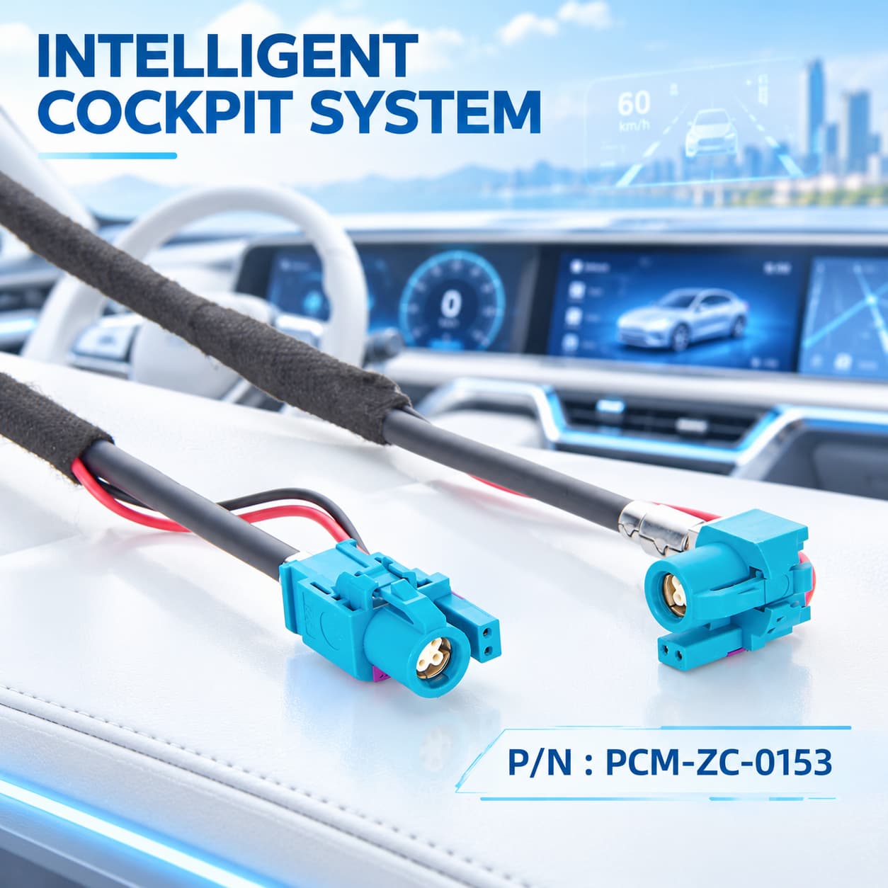
Pain Points
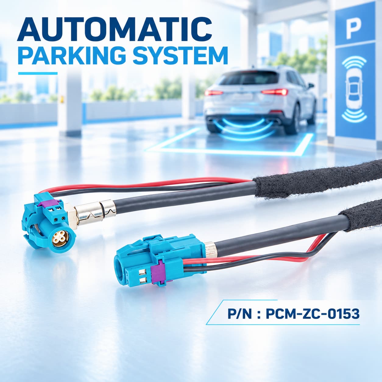
What Is the Difference Between Straight and 90° Right-Angle HSD ?
The main difference between straight and 90° right-angle HSD connectors is cable-exit direction and installation clearance rather than signal function. A straight HSD connector routes the cable along the connector axis and is suitable where sufficient rear clearance is available.
A right-angle HSD connector redirects the cable by approximately 90° near the interface, reducing installation depth and preventing an excessively tight bend radius.
PCM-ZC-0153 uses a straight-to-right-angle configuration, combining conventional routing at one end with space-optimized cable exit at the other for compact ECUs, cameras, display modules and other space-constrained automotive equipment.
Why Is a 4+2 Pin Architecture Needed ?
Traditional HSD connectors primarily carry high-speed differential data, while cameras, displays, sensors and other electronic modules may also require power, ground, wake-up or control circuits.
A 4+2 Pin architecture integrates four high-speed signal contacts and two auxiliary contacts within one connector system. This reduces the need for a separate power connector, saves PCB and installation space, lowers cable-assembly quantity and simplifies assembly operations.
The integrated design is particularly valuable for space-constrained camera modules, display modules, telematics units and other automotive electronics. The exact function, voltage and current rating of the auxiliary contacts must be verified for each application.

Products Display
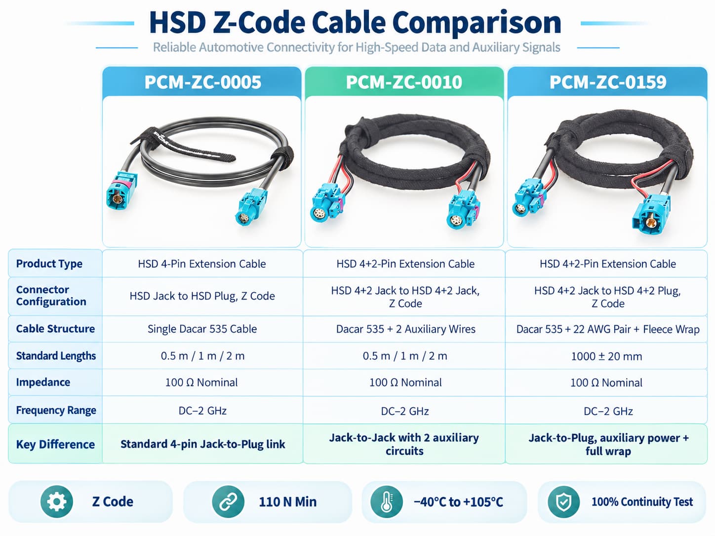
Similar products
Compatibility Statement
Compatibility Verification
PCM-ZC-0153 uses HSD+2 Z Code interfaces designed for compatibility with Rosenberger 99K11D-1D5A5-Z and 99K20K-1D5A5-Z. However, connectors described as HSD 4+2 Pin are not necessarily interchangeable.
Selection requires verification of the complete connector P/N, gender, coding, keying, connector orientation, cable-exit direction, high-speed pinout and electrical definition of the two auxiliary pins. These auxiliary circuits may serve power, ground, wake-up, control or other functions.
Before volume production, device-side connector drawings, pinouts and mating-interface information should be provided for mechanical and electrical compatibility verification.
Technical Compatibility Notice
High-speed cable compatibility must be validated at mechanical, electrical and system levels. Verification should cover gender, coding, keying, locking, pinout, 100Ω differential impedance, auxiliary-pin definitions, shielding, grounding, PHY, SerDes, protocol, data rate, cable length, insertion loss, return loss and the complete link budget.
PCM-ZC-0153 is a passive cable assembly that provides physical paths for differential signals and auxiliary circuits. It performs no protocol conversion, SerDes conversion, retiming or signal processing. Therefore, successful mechanical mating does not confirm matching electrical definitions or protocol compatibility. The complete link must be validated against the original equipment requirements.
Product Comparison and How to Select the Right Cable ?
Verify the Complete P/N, Gender and Z Coding
The first step is not simply determining whether the interface is HSD, but verifying the complete connector P/N.
PCM-ZC-0153 uses interfaces corresponding to the 99K11D-1D5A5-Z and 99K20K-1D5A5-Z configurations. The equipment-side interface must therefore mate correctly with the jack structure, while Z Coding and mechanical keying must also match completely.
Selection should never be based solely on a water-blue housing or similar external appearance.
Verify the Four Signal Pins and Two Auxiliary Pins
The 4+2 Pin architecture includes both a high-speed signal section and an auxiliary circuit section, and each must be verified independently.
The high-speed section requires confirmation of the pinout and actual communication architecture used by the equipment.
The auxiliary section requires verification of power, ground or control definitions as well as permitted voltage and current.
Even if two connectors are mechanically identical, they are not directly interchangeable when auxiliary-pin polarity, function or high-speed pin assignment differs.
Select Straight or Right-Angle According to Installation Space
When sufficient clearance is available behind the interface, a straight configuration normally provides the most straightforward routing path.
When the equipment is positioned close to the vehicle body, enclosure, PCB or another module, a 90° right-angle configuration should be evaluated to determine whether it can reduce installation depth and prevent excessive cable bending.
The required 90° cable-exit orientation must also be confirmed, such as cable down, cable left, cable right or another direction. Specifying only "Right Angle" without defining the actual exit direction may result in an incorrect configuration.
Select the Cable According to Protocol, Length and Link Budget
The standard PCM-ZC-0153 length is 1m. Customized 2m, 3m, 5m or other lengths can be evaluated, but a high-speed link should not simply be extended according to mechanical distance.
As cable length increases, insertion loss, return loss, signal integrity, EMC and the complete link budget should be re-evaluated.
For GMSL, FPD-Link, LVDS or other high-speed SerDes systems in particular, the final permissible length should be confirmed according to chipset-vendor or OEM link requirements.
Customization Capabilities
↕ Custom IX Connector
IX connector models, codings, genders and termination structures can be customized according to the target equipment.
□ Custom RJ45 Panel Interface
RJ45 female interfaces can be customized by category, shielding, orientation and panel-mount design.
◉ Custom Pin Mapping
Custom IX-to-RJ45 pin mapping and differential-pair routing can be developed from customer drawings.
⚙ Custom CAT6A Cable
Cable gauge, diameter, shielding, jacket material and color can be customized.
⌘ Custom Cable Length
Custom cable lengths can be produced according to the internal equipment layout.
◇ Custom Shielding
Foil, drain-wire, braid and connector-shell termination can be optimized for EMC requirements.
Product FAQ
What Does "+2" Mean in HSD 4+2 Pin ?
"+2" represents two additional auxiliary contacts in addition to the four high-speed signal contacts.
Depending on the system, these contacts may be defined as power, ground, control or other auxiliary functions. Their exact purpose must be determined from the equipment pinout; the two auxiliary pins should not be assumed to have identical functions across all HSD+2 devices.
What Is the Difference Between 99K11D-1D5A5-Z and 99K20K-1D5A5-Z ?
Both belong to the HSD+2 jack family and use Z Coding. Their primary structural difference is the cable-exit geometry.
99K11D-1D5A5-Z is a straight jack;
99K20K-1D5A5-Z is a right-angle jack.
They therefore address different installation directions and spatial requirements rather than representing completely different data protocols.
Can the 90° Connector Be Oriented in Any Direction ?
No. Not all 90° connector configurations should be considered identical.
Right-angle HSD connectors may be available with cable-down, cable-left, cable-right or other orientations. The correct direction must be confirmed according to the equipment-interface orientation and actual harness-routing path.
A 3D drawing, equipment-interface photograph or installation-orientation diagram is recommended for customized projects.
Can the 1m Version Be Changed to 2m, 3m or 5m ?
Customized cable lengths can be produced.
However, the fact that a longer cable can be mechanically manufactured does not guarantee stable operation at the same data rate in the target high-speed system.
After increasing cable length, insertion loss, return loss and complete channel performance should be revalidated for the target protocol.
Why Is PET Fleece Wrapping Used ?
PET fleece is mainly used for harness surface protection and NVH improvement.
Around automotive cabins or electronic modules, a harness may contact plastic components, brackets or housings. Fleece wrapping helps reduce friction noise and surface abrasion.
However, it is not equivalent to a waterproof jacket and does not automatically provide an IP rating.
Can an HSD+2 Cable Be Used as a Protocol Converter ?
No.
PCM-ZC-0153 is a passive cable assembly that simply carries the corresponding high-speed signals and auxiliary circuits from one end to the other.
It does not contain a PHY, SerDes, MCU, repeater or protocol-conversion electronics.
If the devices at the two ends use different communication protocols, changing the cable alone cannot perform protocol conversion.