Micro-Fit 3.0 8-Pin to Open-End Power and Signal Cable Assembly: Features, Applications and Selection Guide
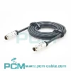
PCM-0877 is a 1.5m Micro-Fit 3.0 8-pin to eight-wire open-end power and signal harness using a Molex 43025-0800 connector and UL2464 20AWG×8C PVC cable. Tinned open wires support PCB soldering, terminal connection and OEM processing.
Modern industrial equipment, robots, controllers, power modules and test systems often need to carry multiple power, control, status and sensor circuits in limited internal space.
PCM-0877 combines a Molex Micro-Fit 3.0 8-pin receptacle with UL2464 20AWG×8C cable and eight stripped and tinned open conductors.
This configuration provides a standardized pluggable Micro-Fit interface while retaining maximum flexibility at the equipment side for PCB soldering, terminal connection, power-module wiring and OEM harness integration.
Quick Product Introduction
The standard structure of PCM-0877 is:
Molex Micro-Fit 3.0 43025-0800 8-Pin Dual-Row Receptacle → LDPE Inner Mold → Black PVC 45P MA-001 Overmold → UL2464 20AWG x 8C Cable → 8 Independent Color-Coded Wires → Strip 4+0.5mm + Tin
| Product Name | Molex 8-Pin HSG to Open-End Cable Assembly |
| Premier Cable P/N | PCM-0877 |
| Configuration | 8-Pin Connector to 8-Core Open End |
| Overall Length | 1500+25mm |
| Open-End Length | 25+5mm |
| Cable Color | Black |
| Cable | 20AWG×8C |
| Cable OD | 6.5mm |
Why Is Micro-Fit 3.0 Suitable for Mixed Power and Signal Wiring?
|
Micro-Fit 3.0 consolidates power, ground, control and status circuits within a compact connector, reducing separate interfaces and simplifying internal wiring and maintenance. Its multi-circuit architecture suits industrial controls, robotics and embedded systems. When power and sensitive signals share a harness, designers should evaluate electromagnetic coupling, grounding, return paths and current transients.
Appropriate pin allocation, shielding and cable routing can help reduce interference and maintain reliable signal performance.
|

What Is Micro-Fit 3.0?
Micro-Fit 3.0 is a compact power and signal connector system developed by Molex with a 3.00mm centerline. It supports wire-to-wire and wire-to-board connections, with single-row, dual-row and multiple circuit configurations. Polarized housings and mechanical locking features help prevent incorrect mating and improve connection security in equipment exposed to vibration or routine maintenance.
Compared with larger traditional power connectors, Micro-Fit 3.0 enables multiple circuits to fit within limited PCB and enclosure space. Typical applications include industrial controls, robotics, test equipment and embedded electronics.
Actual current, voltage and wire-gauge capabilities depend on the selected terminals, connector part numbers and operating conditions.
What Is an 8-Pin Dual-Row Configuration ?
PCM-0877 uses a 2×4 dual-row configuration, with four contacts in each row and eight independent circuits in total. Compared with a single-row eight-pin connector, the dual-row layout reduces overall connector width and increases connection density within limited PCB and equipment space.
It also supports organized cable routing and centralized interface management. The eight circuits may be assigned to power, ground, control or sensor signals according to the equipment design, including combinations of low-voltage power and control lines.
However, eight pins define only the circuit count, not a fixed pinout or electrical function. Wiring, polarity and current allocation must follow the customer's wiring diagram and system requirements.
The 3.00mm pitch refers to the center-to-center spacing between adjacent contacts at the mating interface.
It defines connector geometry and density rather than conductor diameter.

Pain Points
Core Product Value

PCM-0877
The core advantages of PCM-0877 can be summarized as:
◆ Standard Interface and Compact Wiring
The Molex 43025-0800 eight-circuit Micro-Fit 3.0 receptacle combines with 20AWG×8C cable to consolidate power and signal wiring, reduce interface space, and provide polarized, locking mating.
◆ Flexible Open-End Integration
The P2 open end supports PCB soldering, terminal installation, power-module wiring or secondary connector assembly, allowing OEM projects to customize termination methods and pin assignments for different equipment requirements.
◆ Color-Coded Wiring and Molded Protection
Eight color-coded conductors simplify pin identification and wiring inspection. LDPE inner molding and PVC overmolding reinforce the connector-to-cable transition, helping reduce assembly errors and mechanical stress from bending or pulling.
◆ Standard Length and OEM Customization
The standard 1500±25mm length supports inter-module routing in control cabinets, robotics and test equipment. Cable length, pinout, termination methods and labeling can be customized to accommodate specific OEM equipment layouts.

Products Display

Similar products

Compatibility Statement
Compatibility Verification
PCM-0877 uses the Molex 43025-0800 Micro-Fit 3.0 dual-row, eight-circuit receptacle housing with 3.00mm pitch, polarization and a mating lock, rated from -40°C to +105°C. Verify the mating part number, gender, terminal system, wire gauge and pinout.
Similar appearance or eight contacts does not guarantee compatibility; power and signal assignments must follow the equipment wiring diagram.
Technical Compatibility Notice
PCM-0877 is rated at 300VAC and 3.5A per contact. Simultaneous loading of all eight circuits requires evaluation of temperature rise, ambient conditions, crimp quality, contact resistance and heat dissipation.
The Micro-Fit platform's maximum 600V and 8.5A ratings must not be applied directly to the finished assembly; ratings depend on the actual terminals and validation. UL2464 cable identification does not establish UL Listed certification for the complete assembly.
How to Choose the Correct Cable ?
Verify Mating Connector and Circuit Count
Verify that the equipment actually uses an eight-circuit, dual-row Micro-Fit 3.0 interface and confirm the exact mating Molex part number. Selection should not be based only on the appearance of an eight-pin black connector.
Verify Pin Assignment and Power/Signal Allocation
Define the electrical function of every circuit in a complete Pin 1-to-Pin 8 wiring table. Mixed power and sensitive signal circuits should also be evaluated for grounding and noise coupling.
Evaluate Current, Temperature Rise and Voltage Drop
PCM-0877 is rated up to 3.5A per contact, but system design should also consider simultaneous loaded circuits, ambient temperature, cable bundling and voltage drop across the 1.5m cable.
Verify Whether Tinned Open Ends Match the Secondary Termination
Tinned open ends are convenient for PCB soldering, but secondary crimp or terminal applications should be checked against the target terminal requirements. Bare stripped, ferruled or pre-crimped versions can be customized when required.
Customization Capabilities
↕ Micro-Fit Circuit Count and Connector Customization
Different Micro-Fit circuit counts and receptacle, plug or PCB-header configurations can be developed according to the target equipment, using exact Molex part numbers for compatibility verification.
□ Wire Gauge and Cable Construction Customization
Wire gauge and cable construction can be customized according to current, voltage-drop, flexibility and equipment-space requirements, with terminal compatibility and current rating revalidated after any conductor change.
◉ Cable Length Customization
Custom lengths can be produced according to OEM equipment layouts, with voltage drop and thermal performance rechecked for longer high-current versions.
⚙ Open-End Termination Customization
The open end can be customized with bare stripping, tinning, ferrules, ring terminals, fork terminals, quick-disconnect terminals, PCB terminals or another connector.
⌘ Pinout and Conductor Color Customization
Pin mapping, power and ground assignment, conductor colors, wire numbering, heat-shrink identification and labels can be customized according to the customer's electrical drawing.
◇ OEM/ODM Overmolded Harness Development
OEM/ODM harnesses can be developed with customized inner molds, outer molds, strain relief, cable-exit direction, labels and packaging, together with continuity, insulation, hi-pot, voltage-drop, contact-resistance, pull and temperature-rise testing.
Product FAQ
Is 43025-0800 a Micro-Fit 3.0 Part ?
Yes. Molex identifies 43025-0800 as an eight-circuit dual-row Micro-Fit 3.0 receptacle housing.
Can It Carry Power and Signals Together ?
Yes, circuits can be assigned to both power and signals, provided noise and grounding are properly managed.
Why Are the Open Ends Tinned ?
Tinning makes the stranded conductor easier to solder and keeps individual strands organized.
Can It Connect Directly to a PCB ?
Yes. The tinned conductors can be soldered to suitable PCB pads or through-holes according to the PCB design.
Can Shorter Lengths Be Made ?
Yes. Shorter lengths can be produced for compact equipment layouts.
Why Use Both LDPE Inner Mold and PVC Overmold ?
The inner mold stabilizes the internal termination while the outer mold provides strain relief and mechanical protection.