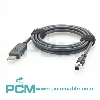
USB 3.0 A to Micro B Right Angle Industrial Camera Cable :
Features Applications And Selection Guide
Explore USB 3.0 A to Micro B right angle cables for industrial cameras, industrial PCs, and image acquisition hosts. Learn about compatibility, data transfer, cable routing, installation clearance, selection, and customization for machine vision and automation systems.
Product Introduction
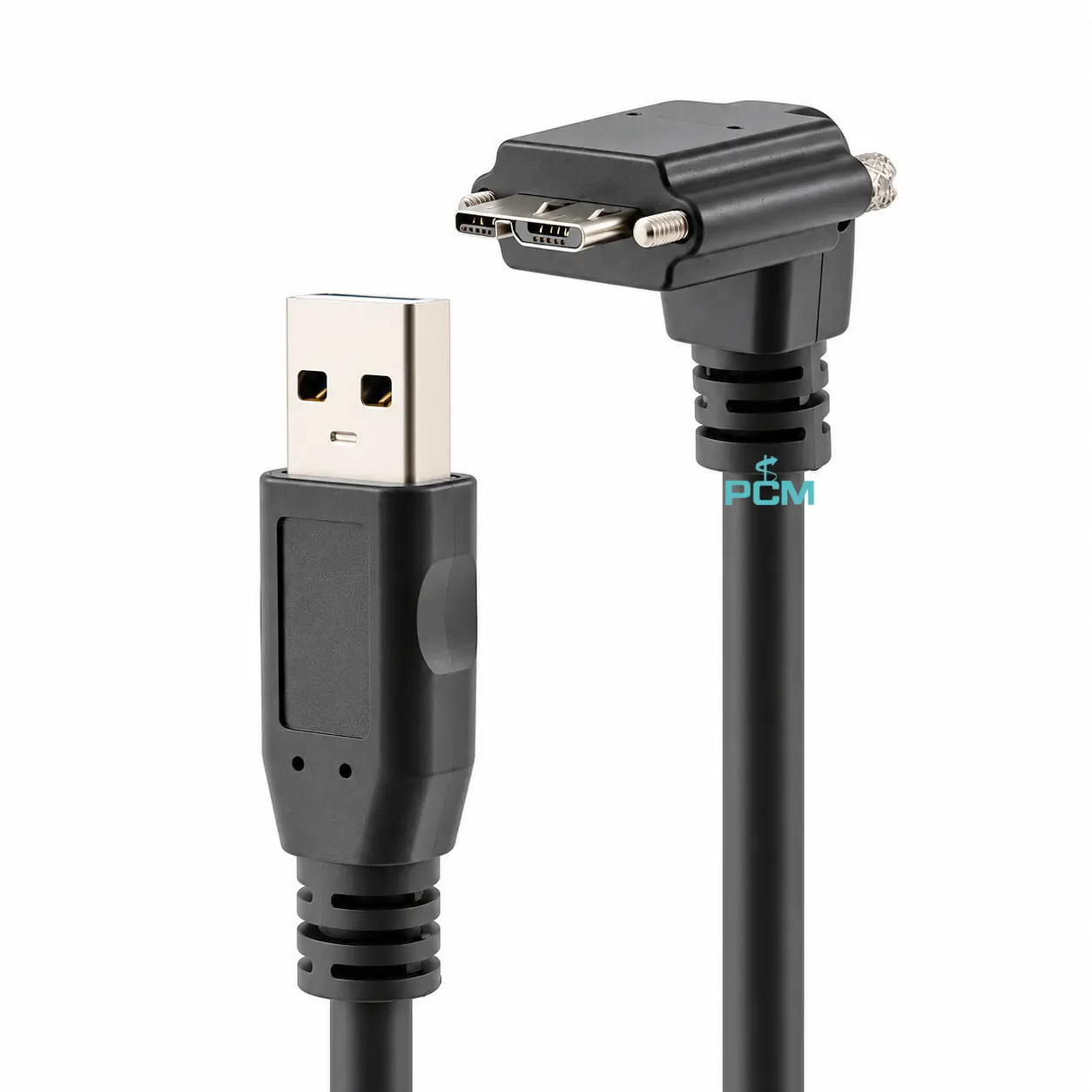
What Is an USB 3.0 A To Micro B Right Angle Industrial Camera Cable ?
The USB 3.0 A to Micro B right angle industrial camera cable connects compatible industrial cameras to computers or image acquisition hosts for USB data transfer.
Unlike a straight connector, its right angle design redirects the cable after mating, helping reduce clearance needed behind the port and route the cable along equipment edges or cable channels. The exit direction depends on connector design and installation orientation.
Why Is the USB 3.0 Micro B Interface Not Freely Interchangeable ?
This cable connects a host via USB Type A and an industrial camera via USB 3.0 Micro B. USB 3.0 Micro B has an extra contact section for SuperSpeed signals and differs physically from USB 2.0 Micro B.
Verify both ports, the camera model, manual and original cable. For replacements or bulk orders, test a sample for fit and data transfer; insertion alone does not guarantee the intended USB mode.
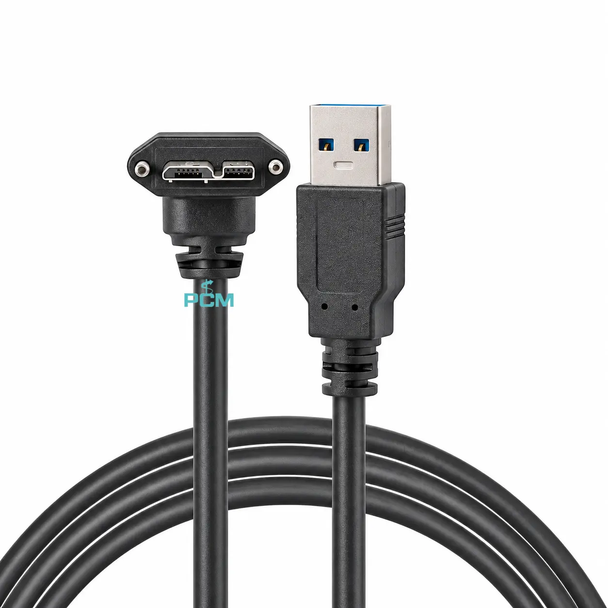
How to Select the Right USB 3.0 A to Micro B Right Angle Industrial Camera Cable ?
Confirm the camera model, USB 3.0 Micro B port, and host USB Type A interface. Check elbow orientation and clearance, measure cable length along the actual route, and verify USB compatibility for the required resolution and frame rate. Test a sample for fit and data performance before bulk orders.
Core Product Value

◆ Right Angle Routing Saves Installation Space
The right angle connector redirects the cable near the port, reducing space needed behind the interface. It offers more routing options when cameras are mounted close to enclosures, brackets, or side panels.
◆ Reduces Interference Near the Connector
Choosing the suitable elbow direction helps route the cable around adjacent ports, brackets, and enclosure edges. This can reduce layout conflicts in compact systems with limited clearance and closely spaced connectors.
◆ Clarifies the Two USB Connection Interfaces
The USB Type A to Micro B configuration defines the connection at each end, helping installers identify the host and camera interfaces. Checking ports before assembly can reduce connector selection and wiring errors.
◆ Supports Image Transfer and Maintenance
When the camera, host, and cable meet USB requirements, the assembly provides a data path for image capture and processing. A cable route and suitable length also simplify installation, inspection, and maintenance.

Product Customization Capabilities
Connector and Elbow
Choose USB A, Micro B, elbow end and exit direction to match installation needs.
Cable Length
Set cable length to match the route, bends, mounts, and service slack allowance.
Cable Construction
Specify shielding, diameter and flexibility to meet USB signal demands reliably.
Jacket and Flexibility
Select jacket and flexibility for static, bending, or moving installation needs.
Strain Relief Design
Customize the boot and strain relief for clearance and reduced cable end stress.
OEM Bulk Production
Plan OEM labels, packaging, and batch tracking; confirm MOQs and delivery dates.
Product FAQ
What is the difference between USB 3.0 Micro B and standard Micro USB ?
USB 3.0 Micro B has an extra contact section for SuperSpeed and differs physically from USB 2.0 Micro B. Check the camera port and manual before choosing a replacement cable.
Can This Cable Carry Data and Bus Power ?
USB can carry data and bus power when supported. Confirm camera voltage and current needs, host port capability, and cable suitability; connector names alone do not define power limits.
How Do You Choose the Right Elbow Direction ?
Choose the elbow direction based on camera mounting, port orientation, and the planned cable route. Check clearance around the enclosure, brackets, and nearby cables using a drawing or sample.
Why Is Image Transfer Unstable After Connection ?
Unstable image transfer may stem from poor mating, incompatible ports, USB mode limits, cable performance, or software settings. Check each and compare with a verified cable to isolate the cause.