TNC Male To N Male RG58 RF Coaxial Cable:
Features Applications And Selection Guide
Learn how a TNC male to N male RG58 RF coaxial cable combines 50 ohm impedance RG58 coaxial construction gold-plated contacts and VSWR below 1.5 for reliable RF signal transmission between radio equipment antennas wireless communication terminals and RF modules This guide covers product structure working principle applications compatibility selection and customization.
Quick Product Introduction
| Product Name: | TNC Male to N Male RG58 RF Coaxial Cable |
| Premier Cable P/N: | PCM-SHM-0011 |
| Connector A: | TNC Male |
| Connector B: | N Male |
| Cable Type: | RG58 Coaxial Cable |
| Product Category: | RF Coaxial Cable |
| Cable Length: | 6 FT |
| Characteristic Impedance: | 50Ω |
| Contact Plating: | Gold Plated |
| VSWR: | <1.5 |
TNC to N Integrated Cable vs Adapter Plus Separate Cable
| Comparison | Integrated TNC to N RG58 Cable | Adapter Plus Separate Cable |
| Interface Conversion | Direct TNC to N connection | Additional adapter required |
| Installation | Simpler cable routing | More components to install |
| Installation Space | More compact | Longer connector stack |
| Maintenance | Fewer points to inspect | Multiple connection points |
| Applications | OEM equipment, fixed cabling and volume projects | Testing, temporary conversion and interface reuse |

What Is a TNC Male to N Male RG58 RF Coaxial Cable ?
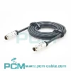
A TNC male to N male RG58 RF coaxial cable is a 50 ohm RF interconnection assembly.
Its basic structure can be described as:
TNC Male Connector + RG58 50 Ohm Coaxial Cable + N Male Connector
The TNC male end connects to equipment with a TNC female interface while the N male end connects to antennas RF devices or wireless terminals The RG58 coaxial structure maintains 50 ohm impedance and shielding for RF transmission antenna extension interface conversion RF testing and OEM connections.
How the Product Works
The RF signal enters through the TNC connector travels along the RG58 center conductor and uses the outer shield as the return path and electromagnetic shielding.
It then exits through the N type connector to an antenna RF module or wireless device The signal path should maintain 50 ohm impedance continuity Impedance mismatch can cause reflections higher standing waves and reduced transmission efficiency, so connector type impedance frequency and system requirements must all be verified.
.

Common RF Cable Problems
Multiple adapters increase connection points installation space and maintenance requirements.
Core Product Value

PCM-SHM-0011
The core advantages of PCM-HD-0011 can be summarized as:
◆ Integrated Connection Simplifies RF Systems
The integrated TNC male to N male design connects different RF interfaces directly reducing extra adapters and intermediate cables This helps lower the number of connection points and simplifies cabling in fixed equipment antenna systems and OEM projects.
◆ Maintains 50 Ohm RF Transmission
The cable is designed for 50 ohm RF systems and supports signal transmission between compatible wireless antenna and RF equipment Proper impedance continuity helps reduce unnecessary reflections and maintain consistent system connectivity.
◆ Suitable for Cabling and Antenna Extension
The standard length of approximately 1.83 meters supports many equipment to antenna connection and positioning needs while reducing temporary cable combinations Other lengths can be selected according to actual equipment layout.
◆ Supports OEM Customization and Volume Supply
For OEM equipment and volume projects connector type cable length cable specification and installation requirements can be customized Integrating these elements into one RF cable assembly can simplify procurement assembly and material management.

Products Display

Similar products

Compatibility Statement
Connector and Impedance Compatibility
- Before purchasing confirm that the equipment uses a compatible TNC female interface the opposite side uses an N female interface and the complete RF system is designed for 50 ohm impedance Physical connector fit alone does not guarantee compatibility in impedance frequency or transmission performance.
Frequency and Environment Requirements
- Operating frequency cable length allowable insertion loss and installation environment should also be verified For high-frequency long distance waterproof temperature resistant flexible or mechanically demanding applications the cable assembly should be selected or customized according to equipment specifications and complete RF link requirements.
How to Select the Correct TNC to N RF Coaxial Cable ?
Confirm Connectors and System Impedance
Confirm that the two ends use compatible TNC female and N female interfaces and verify that the equipment antenna and complete RF path use 50 ohm impedance.
Confirm Frequency and Transmission Loss
Evaluate the RG58 cable and connector performance according to operating frequency Higher frequencies and longer distances generally require closer attention to attenuation and total insertion loss.
Confirm Cable Length and Installation Layout
The standard length is approximately 1828.8 ±20 mm Select cable length according to equipment spacing and routing to avoid installation problems or unnecessary RF loss.
Confirm Environment and Custom Requirements
For outdoor industrial or mobile applications confirm water resistance temperature resistance oil resistance flexibility and mechanical strength Custom connectors lengths and jackets can also be specified.
Customization Capabilities
↕ Connector Options
TNC, N type and other RF connector combinations, orientations and genders can be customized.
□ Cable Length
Cable length can be customized for equipment spacing, cabinet layout and antenna position.
◉ Coaxial Cable
RG58 or other 50 ohm cables can be selected by frequency, loss and flexibility needs.
⚙ Mounting Design
Straight, right-angle and other mounting structures can be customized for limited spaces.
⌘ Label Packaging
Labels, length markings, packaging and OEM information can be customized for volume orders.
◇ Volume Supply
Specifications can be confirmed by drawings, BOMs or samples for volume and long-term supply.
Conclusion:
PCM-SHM-0010 TNC male to N male RG58 RF coaxial cable is a finished 50 ohm RF assembly combining connector conversion, RF signal transmission and equipment cabling.
The standard 6 ft cable features VSWR below 1.5 and is suitable for wireless equipment, antennas, RF modules and OEM devices. Selection should consider connector type, impedance, frequency, length, loss and installation environment, with custom cable options available.
Product FAQ
Does It Fit All Devices ?
Connector names alone are not enough. Gender, 50 ohm impedance, frequency and installation conditions must match.
What Is the Standard Length ?
he standard length is 1828.8 ±20 mm, approximately 1.83 meters or 6 feet.
Can Length Be Customized ?
Cable length can be customized according to equipment spacing, routing and installation allowance.
What Does VSWR Below 1.5 Mean ?
Lower VSWR generally indicates better impedance matching and lower RF signal reflection.
Can It Extend an Antenna ?
It can be used for antenna extension when connectors, impedance, frequency and loss requirements match.
Is OEM Customization Available ?
Connector, length, cable, labeling and packaging customization are available for OEM volume supply.