What Does This Article Cover?
Modern marine electronics such as GPS receivers, chartplotters, multifunction displays, engine monitoring systems and onboard sensors need to exchange navigation and equipment data over a shared network.
NMEA 2000 uses a CAN-based differential communication architecture, so network topology and correct bus termination are important to reliable communication.
If the physical ends of a CAN bus are not properly terminated, impedance discontinuities can produce signal reflections that may contribute to communication errors or unstable network behavior.
Using Premier Cable PCM-0853 NMEA 2000 M12 5-Pin Inline Terminator as an example, this guide explains 120Ω termination, Pin 4/Pin 5 wiring, M12 A coding, inline construction, IP67 protection and correct marine-network placement.
Quick Product Introduction
PCM-0853 uses:
M12 5-Pin Male A-Code → Inline Termination Structure → M12 5-Pin Female A-Code
Its core termination circuit is:
Pin 4 ↔ 120Ω / 1/8W Resistor ↔ Pin 5
This means the adapter combines a male-to-female pass-through interface with a 120Ω differential bus termination.
| Product Name | NMEA 2000 Ship Network Direct Terminal Unit |
| Premier Cable P/N | PCM-0853 |
| Connector Type | M12 |
| Coding | A-Code |
| Pin Count | 5Pin |
| Connector Configuration | Male to Female |
| Termination Resistance | 1/8W |
| Housing Material | PVC |
| Applications | GPS, MFD, Chartplotter, Engine Monitoring, Marine Sensors |
Compatibility Statement
PCM-0853 uses an M12 A-coded 5-pin interface and a 120Ω termination resistor intended for compatible NMEA 2000/CAN differential networks.
However, identical M12 5-pin geometry does not guarantee identical electrical assignments.
M12 5-pin connectors are also used in industrial sensors, CAN systems, DeviceNet and proprietary equipment.
Always verify connector coding, pin assignment, differential-pair location and termination requirements before installation.


Technical Compatibility Notice
PCM-0853 is a passive bus terminator that provides a 120Ω load across the differential data pair.
It does not amplify CAN signals, convert protocols, repair incorrect wiring or replace network splitters or isolators.
Most importantly:
More terminators do not mean better network performance.
A conventional CAN backbone normally uses one 120Ω termination at each physical end.
Two 120Ω resistors in parallel result in an approximate effective resistance of: 60Ω
across the differential pair.
Adding extra termination to an already correctly terminated network may overload the bus.
Basic Product Knowledge
What Is an NMEA 2000 Marine Network ?
NMEA 2000 is a marine networking architecture used to exchange navigation, engine and sensor information among compatible onboard electronic devices.
Typical devices include GPS receivers, chartplotters, MFDs, engine monitors, autopilot systems and marine sensors.
Because the physical network uses CAN-based differential communication, backbone topology, branches and termination are important design considerations.
What Is CAN Bus Signal Reflection ?
Signal reflection occurs when a high-speed waveform encounters a significant impedance discontinuity.
Common causes include unterminated cable ends, inappropriate branches, mismatched cabling or incorrect termination.
Reflections can distort differential waveforms and contribute to intermittent communication or data errors.
Pain Points and Product Value
Challenge 1:
Incorrect Number of Terminators
Too little termination can leave the bus mismatched, while excessive termination increases bus loading.
PCM-0853 should therefore be placed according to the actual network topology.
Challenge 2:
Additional Components Increase Installation Complexity
The inline design combines connection and termination into a single compact component.
Challenge 3:
Marine Vibration Can Affect Connections
M12 threaded locking helps maintain mechanical retention in environments exposed to engine vibration and vessel movement.
PCM-0853 NMEA 2000 Inline 120Ω Terminator
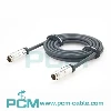
The PCM-0853 adopts an M12A 5-pin male-to-female connector structure with internal integration between Pin 4 and Pin 5: 120/1/8W terminal resistor
The product uses copper contacts with gold plating treatment;external parts use PVC protective structure, and internal parts use LDPE for insulation and structural protection.
The M12 threaded locking can improve mechanical retention after correct mating and provide IP67level protection under normallocked connection conditions.


Applications:
Compatible with:
- NMEA 2000 ship backbone network;
- GPS navigation system;
- The chart maker;
- MFD multifunction display;
- Engine monitoring network;
- Ship sensors;
- Compatible with CAN Bus networks that meet Pinout and terminal requirements.
Similar products

Products Display

Inline Terminator vs. Conventional End Terminator
| Item | PCM-0667 Screw Terminal | Traditional Welding XLR | |
| Structure | Male to Female | Usually Single Interface | |
| 120 Resistance | Built-in | Built-in | |
| Does the interface continue to go directly ? | Yes | Usually No | |
| Installation Flexibility | High | Typical End Usage | |
| Volume | Compact | Compact | |
| CAN Terminal Function | Yes | Yes | |
| Network Location Requirements | Must be correctly evaluated | Backbone Line End | |
| Can be installed anywhere on thenetwork | Not recommended | Not applicable | |
| Typical Application | Specific access terminal arrangements | Standard backbone lineterminal |
How to Select an XLR to Screw Terminal Adapter ?
First Confirm XLR Gender
PCM-0667 uses an XLR 3-pin male connector.
Before ordering, confirm the mating connector gender. Equipment with an XLR male interface will require an XLR female adapter instead.
Verify the Pin Assignment
The standard PCM-0667 wiring is 1→1, 2→2 and 3→3.
Equipment using a proprietary pinout may require customized internal wiring, particularly in industrial-control and non-standard XLR applications.
Confirm the Signal Type
Determine whether the application involves balanced analog audio, DMX512, AES digital audio, industrial control or another low-voltage signal.
These systems may share the same connector format but have different electrical requirements.
Confirm Terminal Pitch and Installation Space
PCM-0667 uses PH5.0 mm terminal spacing and measures approximately 55 × 18.8 mm.
For installations inside cabinets or behind equipment, sufficient access for wire insertion and screwdriver operation should be confirmed.
Customization Capabilities
XLR Gender Customization
XLR 3-pin male or female versions can be selected according to the mating equipment.
Custom Pin Mapping
The standard PCM-0667 uses 1→1, 2→2 and 3→3 wiring, while custom pin mappings can be evaluated for proprietary equipment.
Terminal Type Customization
Screw terminals, push-in spring terminals, pluggable terminals and other industrial terminal configurations can be evaluated.
Terminal Pitch Customization
The standard product uses PH5.0 mm spacing, while other pitches can be evaluated for specific equipment or mechanical requirements.
Overmold Color and Material Customization
PVC overmold colors and material options can be customized for equipment identification, channel management or OEM appearance requirements.
Mechanical Configuration Customization
Overall dimensions, terminal orientation and overmold geometry can be optimized for cabinets, enclosures and equipment rear-panel installations.
Frequently Asked Questions
01.What Is an NMEA 2000 Terminator ?
An NMEA 2000 terminator is a passive impedance-matching device installed at the physical end of the network backbone.
PCM-0853 contains a 120Ω / 1/8W resistor across the differential pair to help reduce reflections caused by an unterminated cable end.
02.Why Is 120Ω Termination Used ?
High-speed digital cables behave as transmission lines.
When a differential signal reaches an unmatched physical end, some energy can reflect back into the cable.
A termination load close to the characteristic impedance of the network helps reduce that discontinuity.
A 120Ω resistor therefore provides termination; it does not amplify the CAN signal.
03.What Is an Inline Terminator ?
A conventional end terminator typically has a single network-facing connector.
PCM-0853 instead uses a male-to-female pass-through structure, allowing the connector path to continue while adding a 120Ω termination load.
This is commonly described as an inline, pass-through or feed-through terminator.
Because it can physically be inserted into a cable path, correct network placement must be verified carefully.
04.Does Device Dropout Always Mean a Termination Problem ?
No.
Network instability can result from incorrect termination, bad connectors, damaged cables, power problems, wiring errors, grounding issues or faulty devices.
A terminator is one part of network signal-integrity design, not a universal repair device.
Get In Touch