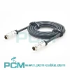
Micro Fit 3.0 6 Pin Power and Signal Cable:
Features Applications And Selection Guide
Explore how the 1.5 m Micro Fit 3.0 6 Pin cable supports power and signal connections in automation, power modules and PCB wiring. Discover its 3.00 mm dual row connector, UL2464 20AWG conductors, molded strain relief, tinned leads, 4.0 A/contact design rating, pinout, compatibility and OEM options.
Quick Product Introduction
| Product Name | Micro-Fit 3.0 6 Pin Male Power/Signal Cable |
| Drawing No | PCM-0875 |
| Cable Type | UL2464 |
| Pitch | 3.00 mm |
| Maximum Voltage | 300V AC |
| Cable Jacket | Black PVC |
| Wire Gauge | 20AWG × 6C |
| Cable Length | 1500 ± 25 mm |
| Rated Current | 4.0 A per Contact |
| Wire End Treatment | Stripped and Tinned |
| Connector Model |
Micro-Fit 3.0, Dual Row, 6 Circuits (Molex 43025-0600) |
Product Comparison
PCM-0875 vs Discrete Wires
| Comparison |
PCM-S-0628 |
Discrete Wires |
|---|---|---|
| Connection Structure | Preassembled 6 Pin Connector | No Preassembled Connector |
| Connector Interface | 3.00 mm Standard Pitch | Requires Separate Selection |
| Wire Termination | Pre Stripped and Tinned | Requires Manual Preparation |
| Strain Relief | Molded Strain Relief | Requires Additional Protection |

What Is a Micro Fit 3.0 6 Pin Cable?
The Micro Fit 3.0 6 Pin cable features a 3.00 mm pitch, dual row, six circuit connector with preassembled termination at one end and flying leads at the other for PCB and controller wiring.
Designed for internal power and low-speed control signals, it is a passive interconnect without voltage conversion, signal amplification, protocol conversion, or electrical isolation.
When to Choose a 6 Circuit Configuration ?
A six circuit configuration integrates power, ground, enable, feedback, and auxiliary control signals into one connector, simplifying wiring.
Six circuits do not mean six independent power channels, and contacts must not be arbitrarily paralleled to increase current. Pin functions and load capacity must be verified against circuit schematics, wiring diagrams, and connector ratings.

Common Wiring Challenges
Complex On Site Assembly
Cutting, stripping, crimping and pin checks raise labor and variation in builds.
Pinout and Polarity Errors
Similar looking wires cause pinout errors and reversed polarity during assembly.
Connector Tail Stress
Unsupported cable ends concentrate bending and pulling stress at wire terminals.
Fixed Wiring Limitations
Fixed end cabling may not match custom pinouts, PCB layouts, or terminal blocks.
Core Product Value

PCM-S-0628
The core advantages of PCM-S-0628 can be summarized as:
◆ Improved Harness Integration
Preassembled connector termination and molded strain relief reduce repetitive assembly steps Standardized wire colors and drawings also help OEMs improve harness consistency.
◆ Consolidated Power and Control Wiring
Six circuits can group power ground, and control signals in one connector reducing separate wiring runs Grounding safety spacing and signal interference still need review.
◆ Flexible Equipment Integration
Flying leads support PCB soldering, terminal blocks, or added connectors to suit device layouts Tinned ends must be checked for compatibility before use with crimp terminals.
◆ Improved Connector Tail Protection
Integrated overmolding supports the connector tail and helps reduce localized pulling and bending stress Cable clamps, bend radius and repeated-flex testing remain essential.

Products Display

Similar product
| Model |
PCM-0763
|
PCM-0876
|
PCM-0885
|
| products |
|
 |
 |
| Product Name |
Micro Fit 3.0 4 pin power/signaling cable |
Micro Fit 3.0 6 Pin Extension Cable |
Micro Fit 3.0 6 Pin Male to Male Cable |
| Cable Specification | 20AWG × 4C | 20AWG × 6C | 20AWG × 6C |
| Cable Type | UL2464 | UL2464 | UL2464 |
| Cable Length | 1500 ± 30 mm |
2000 ± 30 mm |
2000 ± 30 mm |
| Main Difference |
Open-end stripped & tinned leads |
Male to female connector configuration |
Male to male connector configuration |
| Jacket Material | Black PVC | Black PVC | Black PVC |
| Cable OD | 5.5 mm | 5.5 mm | 5.5 mm |

Product Compatibility Statement
PCM-0875 uses a six circuit Micro-Fit 3.0 receptacle housing (Molex 43025-0600). Before mating, verify the matching plug or PCB header, contact terminals, latch design and installation clearance. A 6-pin layout, a 3.00 mm pitch or similar appearance alone does not guarantee mechanical compatibility.
Product Customization Capabilities
Customized length
Standard 1500 ± 25 mm length custom lengths should be checked for voltage drop.
Custom Pinout
Six wire colors and pinouts could be customized; verify continuity and polarity.
Custom Cable Construction
Standard UL2464 20AWG × 6C PVC cable; other gauges require terminal fit testing.
Flying Lead Termination
Standard 4 ± 0.5 mm tinned ends; choose bare wire or ferrules to suit terminals.
Custom Overmold Design
LDPE inner and PVC 45P outer molds; tailor cable exit and the overmold geometry.
OEM Labels and Packaging
OEM labels, part numbers and packaging help large orders and batch traceability.