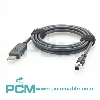
M12 A Code 12 Pin to DB15 I/O Cable :
Features Applications And Selection Guide
Explore the M12 A code 12 pin female to DB15 15 pin male I/O cable for machine vision systems. Learn how it connects compatible vision equipment to a CIO-1400 I/O module, with full guidance on compatibility, pin mapping, cable length, and custom options using Cognex CCB-PWRIO-MOD-05 as a reference.
Product Introduction
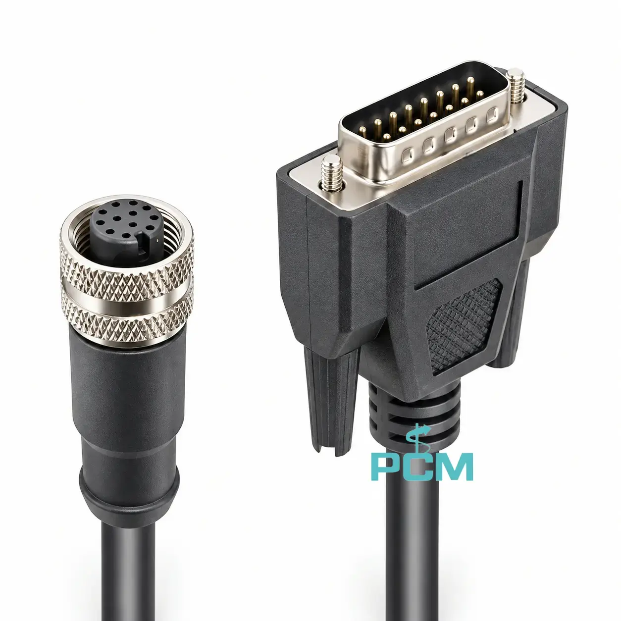
What Is an M12 A Code 12 Pin to DB15 I/O Cable ?
An M12 A code 12 pin female to DB15 15 pin male I/O cable links a compatible vision sensor and I/O module for machine vision control applications.
It carries power, trigger, input and output signals according to the approved pin mapping. This supports signal exchange with external controls. Functions depend on the equipment model, module setup, and a verified wiring diagram. Confirm wiring first.
How Do Trigger, Inspection Result, and Communication Signals Work Together?
In automated inspection, external equipment sends a trigger to start inspection. The vision device outputs inspection status or control signals for a PLC or controller.
The I/O cable carries signals according to the approved pin mapping. For serial communication, verify wiring and port settings. The cable does not define inspection logic; available functions depend on the sensor, I/O module, and system configuration.
How to Choose a Suitable I/O Module Cable ?
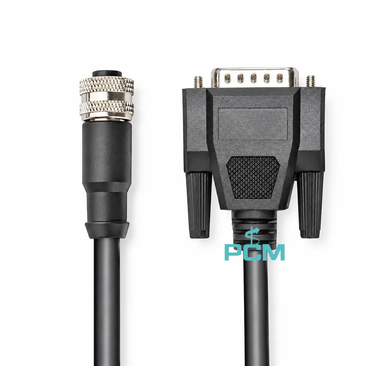
Choose an I/O module cable by confirming device models, compatibility, and connector types (M12 A code 12 pin female to DB15 15 pin male). Verify pin mapping and signal assignments; check cable length, routing clearance, shielding, flexibility, and site conditions. For CIO-1400, consult its manual.
Core Product Value
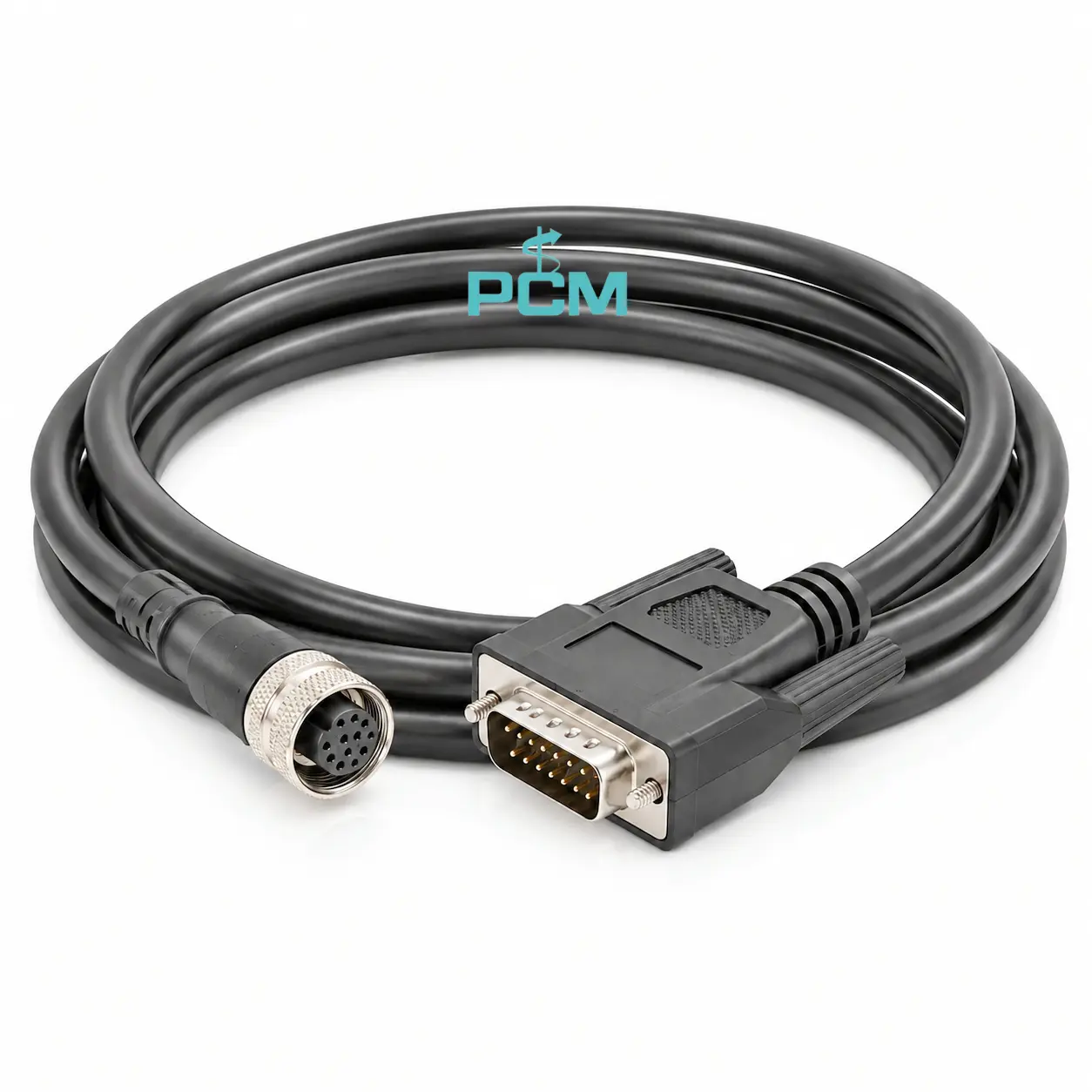
◆ Dedicated Connector Design
This cable combines an M12 A code 12 pin female connector with a DB15 15 pin male connector, providing a dedicated physical link between compatible machine vision equipment and an I/O module for system wiring.
◆ Consistent Signal Connectivity
Its internal conductors connect to connector contacts according to an approved pin map, providing paths for designated power, trigger, input, and output signals. This helps preserve signal assignments across the cable.
◆ Supports Coordinated System Operation
This cable links compatible vision equipment to an I/O module, supporting configured trigger inputs, inspection status outputs, and control signals for automation. Actual functions depend on system configuration.
◆ Easier Installation and Maintenance
The dedicated connector layout helps identify connection points and organize installation. For replacement or maintenance, matching the interface and verified wiring map can reduce rework and the risk of wiring errors.

Product Customization Capabilities
Cable Length
Set cable length to suit equipment layouts, routing, and maintenance needs.
Connector Specifications
Connector options can be custom-built for confirmed interface types and layouts.
Pin Mapping
Pin mapping should follow approved wiring diagrams for the target vision system.
Cable Materials
Cable materials, flexibility, and shielding can match the operating environment.
Testing and Traceability
Set tests and traceability criteria for continuity, pin mapping, and each batch.
OEM Bulk Production
Plan OEM labels, packaging, and batch tracking; confirm MOQs and delivery dates.
Product FAQ
Why Might the Vision System Fail After Installation ?
Causes may include loose connectors, incompatible devices, incorrect pin mapping, power faults, or wrong I/O settings. Check wiring against the official diagram, then test with a verified cable.
How Can I Verify M12 to DB15 Pin Mapping ?
Use the sensor and I/O module wiring diagrams to check each contact assignment. Test continuity, opens, shorts, and miswiring, and use the approved pin map for production and acceptance.
Which Signals Can This I/O Cable Carry ?
The cable carries power, trigger, input, output, or related signals only as defined by the equipment. Actual functions depend on the device setup and approved internal pin mapping.
How Does It Differ from a Flying Lead I/O Cable ?
This cable uses an M12 A code 12 pin female connector and a DB15 connector for an I/O module. A flying lead cable exposes individual wires for terminal-block wiring; the two are not interchangeable.