What Does This Article Cover?
As ADAS, vehicle cameras, intelligent cockpits, sensors and automotive electronic modules become more common, vehicles increasingly require reliable data and power interconnections between different physical interfaces.
PCM-0803 provides:
HSC 4Pin Female → USB 2.0 Type-A Male
This guide explains its cable architecture, differential signaling, power conductors, shielding, compatibility requirements and typical automotive applications.
Quick Product Introduction
PCM-0803 combines an HSC/HSL 4Pin female connector with a USB 2.0 Type-A male plug through a 1m UL2725 shielded cable.
Its internal construction is:
28AWG × 1P + 24AWG × 2C + AEB
allowing differential data transmission and power delivery through one cable assembly.
| Product Name | HSC 4Pin to USB A Car High-Speed Data Cable |
| Premier Cable P/N | PCM-0803 |
| Connector A | HSC/HSL 4Pin Female |
| Connector B | USB 2.0 Type-A Male |
| Cable Length | 1000+30mm |
| Cable Style | UL2725 |
| Signal Wire | 28AWG x 1P |
| Power Wire | 24AWGx2C |
| Cable OD | Approx. 4.5mm |
Compatibility Statement
Mechanical compatibility does not automatically guarantee electrical or protocol compatibility.
An HSC 4Pin interface must have the correct pin assignment, signal type, USB role and electrical definition before it can communicate with a USB Type-A device.
Most importantly:
HSC 4Pin does not automatically mean USB 4Pin.


PCM-0803 is a passive automotive data and power cable.
It does not convert CAN, LVDS, SerDes, automotive Ethernet or proprietary camera protocols into USB.
A camera using an HSC connector is therefore not automatically a USB camera.
The equipment must electrically and logically support the USB interface defined by the cable.
Basic Product Knowledge
What Is an HSC 4Pin to USB-A Automotive Cable ?
An HSC 4Pin to USB-A cable connects a compatible automotive HSC interface to a USB 2.0 Type-A host or device.
The cable simply carries the required differential data and power circuits according to the specified pin mapping.
What Is an HSC/HSL 4Pin Interface ?
HSC/HSL connectors are compact automotive interconnects used for data and power connections between vehicle electronic modules.
However, HSC describes the connector system rather than the communication protocol itself.
Pain Points And Product Value
Challenge 1:
Different Physical Interfaces
PCM-0803 provides a direct physical link between compatible HSC vehicle devices and USB-A equipment.
Challenge 2:
Compact Vehicle Ports vs. Common USB Equipment
HSC provides a compact vehicle-side interface while USB-A offers convenient connectivity to widely used host and test equipment.
Challenge 3:
Separate Data and Power Wiring
Combining the differential data pair and power conductors into one harness simplifies system wiring.
Challenge 4:
Signal and Power Conductors Have Different Requirements
The cable uses different conductor sizes to address the different requirements of high-speed data and power transmission.
Similar products

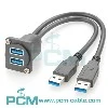
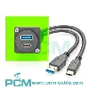
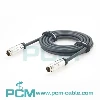
PCM-0803 HSC 4Pin to USB-A Automotive Cable
The standard configuration for PCM-0803 is:
HSC HSL 4Pin Female to 1m UL2725 Cable to USB 2.0 Type-A Male
PCM-0803 combines a 4Pin HSC/HSL female connector with a USB 2.0 Type-A male plug through a 1m UL2725 shielded cable.
It is suitable for compatible automotive camera, sensor, ADAS and vehicle-electronics development applications.

Products Display

HSC-to-USB vs. Standard USB Cable
| Item | PCM-0803 HSC-USB-A | Standard USB 2.0 Cable | |
| Vehicle-Side Connector | HSC 4Pin Female | USB Connector | |
| Host-Side Connector | USB-A Male | USB-A/USB-B / Micro etc. | |
| Automotive Module Connection | More suitable for HSC devices | Depends on interface | |
| Signal Pair | 28AWGx1P | Depends on product | |
| Power Conductors | 24AWGx2C | Depends on product | |
| Shielding | AEB | Depends on product | |
| Cable OD | Cable OD | Depending on model | |
| Main Use | HSCdevice to USB system | USB Device Interconnection |
How to Select an HSC 4Pin to USB Cable ?
Verify the HSC Connector
Verify the exact HSC connector family, gender, coding and mechanical keying before ordering.
Verify the Pin Assignment
Pin mapping must be verified from the actual equipment specification.
Never assume direct numerical pin-to-pin mapping simply because both interfaces have four contacts.
Confirm That the HSC Device Actually Uses USB
Confirm that the HSC-side equipment actually communicates using USB.
A passive cable cannot convert LVDS, GMSL, FPD-Link, CAN or Ethernet into USB.
Verify USB Host and Device Roles
Verify which endpoint operates as the USB host and which operates as the USB device.
A cable does not change USB roles.
Confirm USB Speed Requirements
PCM-0803 is intended for USB 2.0 applications and should not be treated as a USB 3.x SuperSpeed cable.
Verify Power Requirements
Power requirements should be evaluated according to voltage, current, startup load, connector capability and acceptable voltage drop.
Verify Cable Length
The standard PCM-0803 length is 1m.
Longer versions should be validated for USB signal integrity and voltage drop.
Verify Shielding and Grounding
Shield effectiveness depends on the complete termination path between the cable, connector and equipment ground or chassis.
Customization Capabilities
Custom HSC Connector
Different HSC/HSL connector series, genders, codings and locking configurations can be developed for OEM applications.
Custom Pin Mapping
Custom HSC-to-USB pin mapping can be developed from the customer's schematic or interface definition.
Custom USB Connector
Alternative USB connector types can be evaluated according to the required USB protocol and equipment architecture.
Custom Cable Length
Custom lengths are available for vehicle, test-bench and equipment integration applications.
Custom Wire Gauge
Signal and power conductor sizes can be customized according to data, current and mechanical requirements.
Custom Shielding
Foil, braid, drain-wire and connector-shield termination can be customized to suit the target EMC environment.
Frequently Asked Questions
01.What Is USB 2.0 Type-A ?
USB 2.0 Type-A commonly uses VBUS, D-, D+ and GND connections.
D+ and D- form the differential data pair, while VBUS and GND provide the power path.
Final HSC-to-USB pin mapping should always follow the actual wiring drawing.
02.What Is the USB 2.0 Data Rate ?
USB 2.0 High-Speed mode has a theoretical signaling rate of up to 480Mbps.
Actual application throughput is lower and depends on the host, device, protocol overhead and complete link quality.
PCM-0803 should therefore not be marketed as a USB 3.x multi-gigabit cable.
03.Why Use a 28AWG Differential Pair ?
The 28AWG single twisted pair carries the differential data signals.
Balanced twisted-pair construction helps control impedance, reduce noise susceptibility and maintain signal integrity.
04.What Does AEB Shielding Do ?
AEB shielding helps reduce electromagnetic interference affecting the data pair and can also reduce radiated emissions from the cable.
However, shielding alone cannot eliminate all EMC issues; termination, grounding and system design remain important.
Get In Touch