DALSA Genie Nano GigE Camera I/O Cable :
Features Applications And Selection Guide
Explore the DALSA Genie Nano GigE Camera I/O Cable for camera power and signal control. Learn how its 10 pin connector and open wires handle power, triggers, digital outputs and strobe signals, with guidance on wiring, interface matching and OEM cable solutions in industrial vision systems.
Product Introduction

What Is a DALSA Genie Nano GigE Camera I/O Cable?
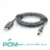
The DALSA Genie Nano GigE Camera I/O Cable connects a camera's 10 pin I/O port to external power and control devices. Its open-wire leads carry DC power, trigger inputs and digital outputs for status feedback or strobe control.
It is used in machine vision systems and automated production lines to link Genie Nano cameras with PLCs, control cabinets and peripheral equipment.
How External Triggering Works with the DALSA Genie Nano I/O Cable ?
External triggering lets a DALSA Genie Nano camera capture images in response to production events. A sensor or PLC sends a signal through the I/O cable's designated wire to the camera's GPI input.
When the signal meets the camera's electrical requirements and trigger settings, the camera acquires an image. Image data is then sent separately to the computer through the GigE Ethernet interface.

How to Choose the Right I/O Trigger Cable ?
To choose an I/O trigger cable, confirm the camera's I/O interface, connector and pinout. Check trigger voltage, polarity, pulse requirements, power and grounding. Match cable length, shielding and flexibility to the installation. Verify each open wire against the wiring diagram before connection.
Core Product Value

◆ Dedicated Connector for Reliable Fit
The dedicated connector matches the camera's I/O interface and provides an electrical path to power and control devices. Its assembled design helps maintain pin alignment and reduces uncertainty during installation.
◆ Integrated Power and Signal Wiring
Power and control conductors share one cable assembly and connect to the camera through a single interface. This reduces separate cable runs and keeps connections to PLCs, trigger devices and lighting controls organized.
◆ Screw Locking for Secure Connections
The screw locking connector holds the cable firmly in place during operation. In production lines and moving machinery, this fastening structure helps reduce loosening or intermittent contact caused by vibration.
◆ Shielding and Open Wire Integration
The shielding helps limit electromagnetic interference, while the open wire end connects individual conductors to terminals or control modules. This supports organized wiring in vision systems and control cabinets.

Product Customization Capabilities
Cable Length
Custom lengths suit camera layouts, control cabinets and cable routing needs.
Pinout and Wiring
Wire assignments follow pinouts for power, ground and I/O signal connections.
Connector Design
Connector designs match camera interfaces, locking and mounting requirements.
Wire End Processing
Wire ends can include stripping, labels or crimp terminals for easier wiring.
Cable and Shielding
Jacket, conductor and shielding options suit varied industrial work settings.
OEM Bulk Production
Plan OEM labels, packaging, and batch tracking; confirm MOQs and delivery dates.
Product FAQ
Can This Cable Carry GigE Image Data ?
No. This I/O cable carries camera power and control signals, not image data. Images travel through the camera's separate RJ45 GigE Ethernet connection to a computer or network switch.
Can I/O Power and PoE Be Used Together ?
Do not use both power sources at once unless the camera manual explicitly permits it. Follow the model's instructions for I/O power or PoE to avoid electrical faults.
Can This I/O Cable Connect to a PLC ?
Yes. The open wire end can connect to PLC terminals for trigger input or camera digital output signals. Check pin assignments, signal levels and common wiring; use isolation if needed.
Can This Cable Support Triggering and Strobe Control ?
Yes, if supported by the camera's I/O configuration. An input receives trigger signals, while an output can signal a strobe controller. Check signal ratings; direct lamp drive may not be supported.