Micro Fit 3.0 4 Pin Male to Male Premolded Cable:
Features Applications And Selection Guide
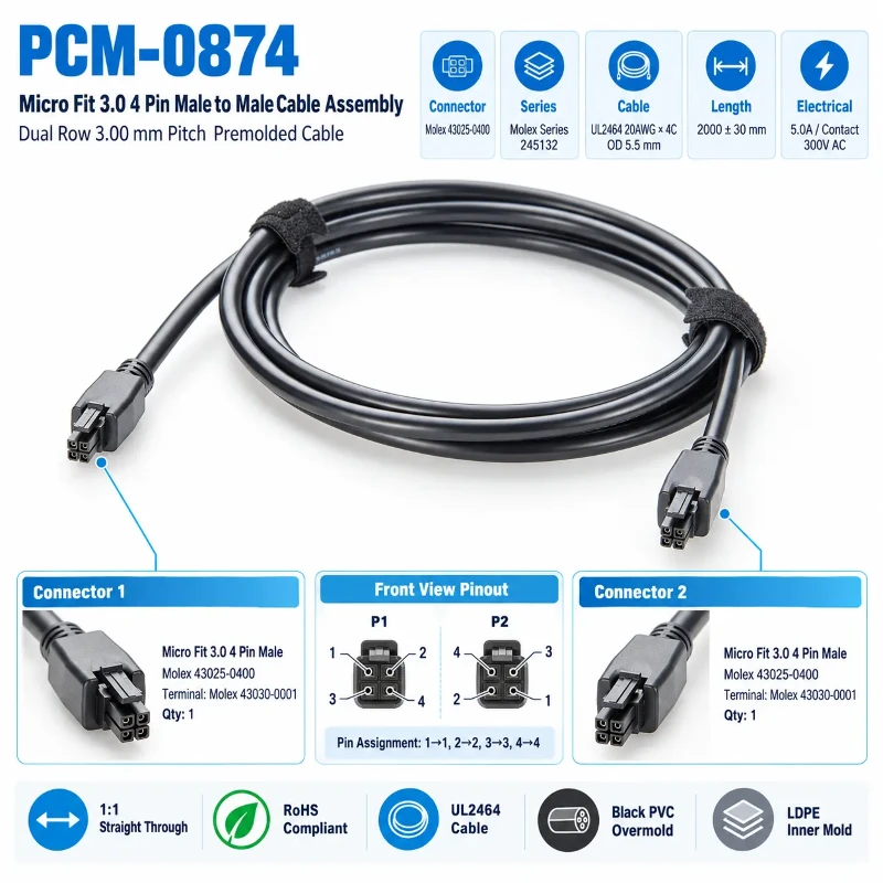
Learn how a Micro Fit 3.0 4 pin male to male premolded cable combines dual row 3.00mm connectors, 20AWG UL2464 cable, 1 to 1 straight through wiring and molded strain relief for industrial control, automation, communication, power systems and internal equipment wiring.
Quick Product Introduction
| Product Name | Micro Fit 3.0 4 Pin Male to Male Premolded Cable |
| Pitch | 3.00 mm |
| Drawing No | PCM-0874 |
| Wire Gauge | 20AWG × 4C |
| Cable Length | 2000 ± 30 mm |
| Rated Current | 5.0 A per Contact |
| Connector Model | Molex 43025-0400 |
| Connector | Dual Row Micro Fit 3.0 4 Pin |
| Wiring | Pins 1–4, 1:1 Straight Through |
Product Comparison
PCM-0874 vs Conventional Crimped Harness
| Comparison | PCM-0874 | Conventional Crimped Harness |
|---|---|---|
| Wiring | Predefined 1 to 1 wiring | Based on harness design |
| Installation | ready for installation | Medium to high |
| Consistency | suitable for standardized production | assembly dependent |
| Maintenance | Modular and easy to replace | Replaceable but less integrated |

What Is a Micro Fit 3.0 4 Pin Cable ?
A Micro Fit 3.0 4 pin male to male premolded cable is a preassembled cable for power or signal interconnection between devices PCM-0874 uses dual row 4 circuit 3.00mm connectors on both ends, 20AWG × 4C cable and 1 to 1 straight through wiring from Pin 1 to Pin 4.
It does not perform protocol or voltage conversion. The assembly is designed for reliable connections between PCB modules, power modules, controllers and automation equipment, with a premolded structure providing improved tail protection and strain relief.
Why Use a 3.00mm Dual Row 4 Circuit Configuration ?
The 3.00mm dual row 4 circuit design provides four independent connections in a compact space, improving interface density. Each circuit can be assigned to power, GND, control or signal lines according to the equipment pin assignment.
It is suitable for PLC modules, controllers, communication equipment and power modules, while final pin functions must follow the device schematic.

Common Issues with Micro Fit 3.0 Connection Cables
Field Crimping Errors
On-site cutting, stripping, crimping and terminal insertion can introduce poor crimps, wrong pin positions or conductor damage.
Pinout Mismatch
Mechanical mating does not guarantee matching pin definitions. Verify power, GND and signal assignments before using straight-through wiring.
Tail Bending Stress
Repeated bending can concentrate stress at the terminal tail. Premolded strain relief helps protect the crimp transition area.
Cable Length Mismatch
Short cables create tension, while excessive length increases routing clutter. Cable length should match the actual wiring path.
Core Product Value
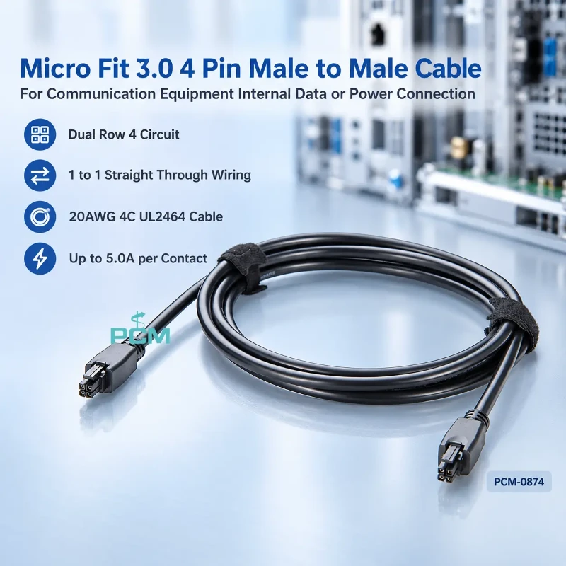
PCM-0874
The core advantages of PCM-0874 can be summarized as:
◆ Improved Connection Consistency
Standardized connectors, terminals, wire gauge and pinout reduce operator-related wiring differences and improve consistency, repeatability and assembly reliability in volume production.
◆ Fewer Assembly Processes
Premolded cables can enter assembly directly, reducing cutting, stripping, crimping, terminal insertion and tail protection steps to improve production efficiency.
◆ Improved Tail Protection
The LDPE inner mold and PVC overmold provide tail protection and strain relief, reducing stress on the crimp area and improving mechanical stability.
◆ Easier Maintenance
Standardized premolded cables can be stocked and replaced as complete assemblies, reducing on-site rework while simplifying maintenance and spare part management.

Products Display
Similar product
| Model |
PCM-HD-0214
|
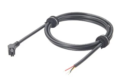
PCM-HD-0221
|
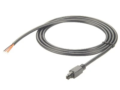
PCM-0763
|
| products | 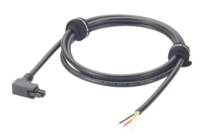 |
 |
 |
|
Product Name |
right angle3.0 mm Pitch 4 Pin Cable | 3.0 mm Pitch 4 Pin Cable Assembly | Micro Fit 3.0 Dual Row 4 Pin Cable |
| Connector Style | Dual-row 4P, right-angle | Dual-row 4P, 45° left-angle | Micro Fit 3.0, straight |
| Cable Spec | UL2464 20AWG×4C | UL2464 20AWG×4C | UL2464 20AWG×4C |
| Cable Length | 1500±30 mm | 1500±30 mm | 1500±30 mm |
| outer diameter | OD 5.5±0.15 mm | OD 5.5±0.15 mm | OD 5.5 mm |
| Key Difference | Right-angle housing | 45° left-angle housing | Straight Micro Fit 3.0 |
| Cable sheathing | black PVC | black PVC | black PVC |
Compatibility StatementCompatibility Verification
Verify Interface and Pinout
- Before purchase, confirm that the equipment uses a compatible Micro Fit 3.0 dual row 4 circuit interface, with correct connector gender and Pin 1 to Pin 4 definitions matching the 1 to 1 straight through wiring. Mechanical mating does not guarantee electrical compatibility.
Electrical and Installation Requirement
- Operating current, voltage, 20AWG wire size, cable length, bend radius and environmental requirements should also be verified. If the device pinout or operating conditions differ, provide the schematic or pin assignment to the cable manufacturer for custom evaluation.
Product Customization Capabilities
Custom Cable Length
Cable length and tolerance can be customized for routing, installation distance and assembly allowance.
Custom Pinout
Straight through, crossover, power and signal pin assignments can be customized to drawings.
Custom Wire and Cable
Wire gauge and cable construction can be customized for current, flexibility and environment.
Custom Connector Combination
Micro Fit to other connector combinations can be evaluated for specific equipment interfaces.
Custom Overmold
Customizable injection molding structure, color, markings, and tail stress relief design.
Custom Labeling and Packaging
Part numbers, labels, barcodes, packaging and volume production can be customized.